
Note: The engine must be cold when removing the cylinder head. Do not remove the head from a hot engine. Use new mounting bolts and a new cylinder head gasket when installing, sealant will be required when installing the camshaft housing. The specified tightening torques only apply to the latest bolts available from Opel. Early bolts must be tightened with a different torque. Please consult with your supplier.
Removing
1. Disconnect the negative cable from the battery.
2. Drain the cooling system as described in Section 3.
3. Disconnect the outlet pipe from the manifold, following Section 4C.
4. The cylinder head can be removed together with the manifolds, or the manifolds can be separated from the cylinder head before removing it, refer to the relevant Chapters of Sections for this 4A, 4B or 4C. If no work is to be done on the intake manifold, it can be unscrewed from the head and fixed, thus eliminating the need to disconnect the associated hoses, pipes and wiring.
5. If the cylinder head must be removed along with manifolds, disconnect all hoses, pipes and electrical wiring from the intake manifold and related components, guided by Sections 4A or 4B. On carbureted models, disconnect the warm air hose from the shroud on the exhaust manifold. Loosen the alternator mountings as described in Section 5, then unbolt the upper alternator mountings from the intake manifold.
6. If the intake manifold must be left in the engine compartment, proceed as described below, otherwise go to step 15.
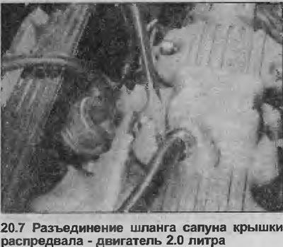
7. Disconnect the air filter line from the heater block on the carburetor or throttle body, or directly from the throttle body (depending on the model), disconnect the breather hose on the camshaft cover that goes to the carburetor or throttle body (depending on the model) (see illustration).
8. On C16NZ2, 1.8 and 2.0 liter models, disconnect the smaller coolant hose from the top of the thermostat housing.
9. On 1.6 liter models (except С16NZ2), disconnect the breather hose (which goes from the camshaft cover to the intake manifold) from the camshaft cover.
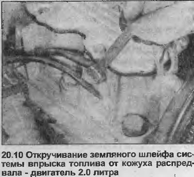
10. On models with fuel injection, unscrew the two ground loops from the camshaft housing (see illustration).
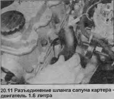
11. On models 1.4 and 1.6 liters (except С16NZ2), disconnect the hose that connects the crankcase breather pipe to the rear of the camshaft housing (see illustration).
12. Loosen the generator fastenings, guided by Section 5, then unscrew the alternator top mount from the intake manifold.
13. Finally, check that all hoses, pipes and wires have been disconnected, then unscrew the fixing nuts, marking the location of the engine lifting bracket, lift the intake manifold from the cylinder head. Make sure the manifold is properly supported, also be careful not to deform any hoses, pipes, wires, etc. that remain connected.
14. Remove the manifold gasket from the cylinder head.
15. If required, remove the exhaust manifold as described in Section 4C.
16. Remove the toothed drive belt and camshaft sprocket as described in Chapter 11.
17. Turn off two bolts of fastening of the top back cover of a driving belt from a casing of a cam-shaft.
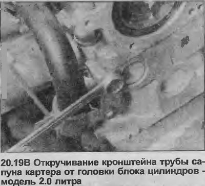
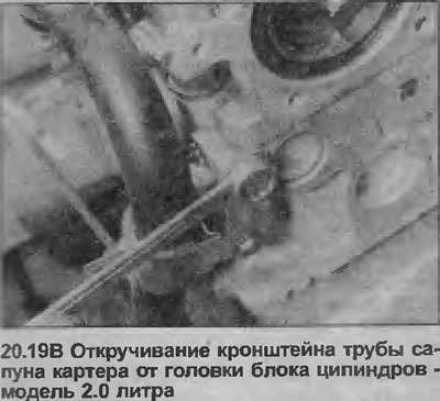
18. Disconnect the high voltage wires from the spark plugs and the ignition coil, noting their location to simplify installation, and remove the cover of the breaker-distributor, being guided Section 5. Where applicable, disconnect the distributor wiring harness.
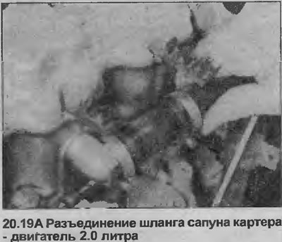
19. Disconnect the hose from the fitting that connects the crankcase breather pipe to the camshaft housing. Remove the bolt securing the crankcase breather pipe bracket to the end of the cylinder head (see illustrations).
20. Disconnect the coolant hoses from the thermostat housing.
21. On carbureted models, disconnect the fuel supply hoses from the fuel priming pump. Seal open ends of hoses to prevent fuel leakage and dirt ingress
22. Finally, check that all relevant hoses, pipes, wires, etc. have been disconnected.
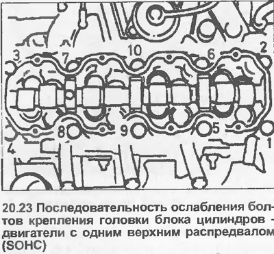
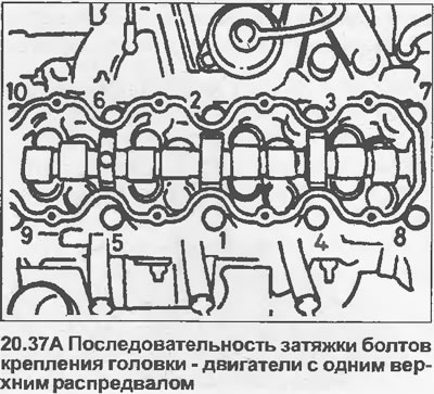
23. Working from outside to inside in a spiral as shown (see illustration), loosen all cylinder head bolts a quarter of a turn. Then loosen all bolts by half a turn, and finally completely loosen and remove the bolts. Remove washers.
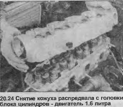
24. Lift the camshaft casing from the cylinder head (see illustration). If necessary, lightly tap the casing with a mallet to release it from the cylinder head. Please note that the camshaft housing is located on the pins.
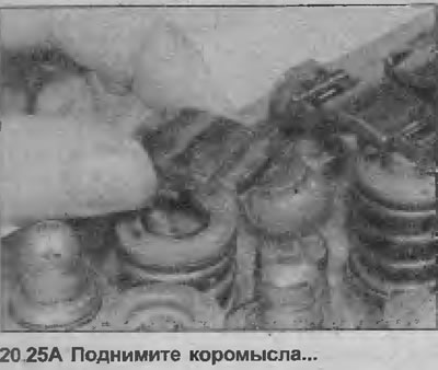
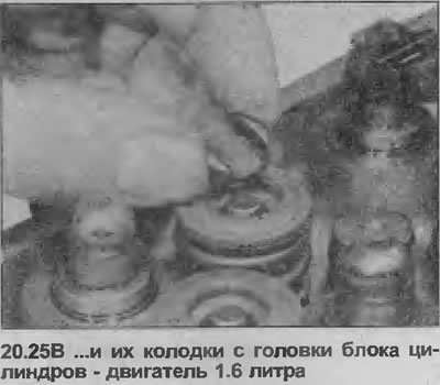
25. Lift the rocker arms and their pads from the head, store them in the order they were removed so as not to mix up during installation (see illustrations).
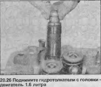
26. Lift the valve lifters from the cylinder head, fold them while standing in an oil bath (see illustration). Make sure the oil is deep enough to completely cover the valve lifters, and hold the lifters so that they can be reinstalled.
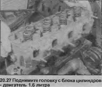
27. Lift the head off the cylinder block (see illustration). If necessary, tap the cylinder head lightly with a mallet to release it from the block. Please note that the cylinder head is located on the pins.
28. Remove and discard the head gasket.
Installation
29. Clean the mating surfaces of the cylinder head and block, the mating surfaces of the camshaft housing and cylinder head. Do not damage the machined surfaces of the head and camshaft housing. Cover cooling passages and other openings with duct tape or rags to prevent dirt and deposits from entering. Remove oil from all bolt holes; if oil remains in the holes, the block may crack as a result of the hydraulic pressure when the bolts are tightened.
30. If required, the cylinder head can be disassembled and checked as described in Chapters 22 and 23, and the camshaft housing can be disassembled as described in Chapter 18.
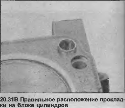
31. Start the installation like this: position the new gasket on the block so that the word "OBEN" or "TOR" could read from above (see illustrations).

32. Having thoroughly cleaned the mating surfaces, position the head on the cylinder block so that the pins fit into their respective holes.
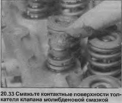
33. Install valve lifters, thrust pads and rocker arms on the cylinder head (to the places where they stood before removal). Liberally lubricate the valve lifter seats with oil, and if new lifters are being installed, submerge each one in a container of engine oil and hand squeeze several times to fill with oil. Lubricate the contact surfaces of the tappets, thrust pads and rocker arms with molybdenum grease (see illustration).
34. Temporarily install the crankshaft sprocket, check that the alignment marks remain in the same positions that they occupied before removing the drive belt (see chapter 11).
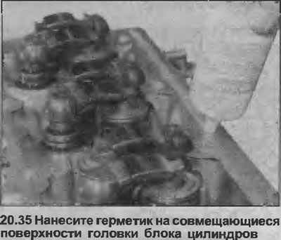
35. Apply sealant (Opel #90094714 or equivalent) on mating surfaces of the cylinder head (see illustration), then install the camshaft housing to the head.
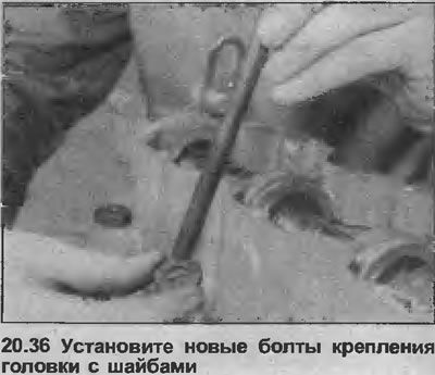
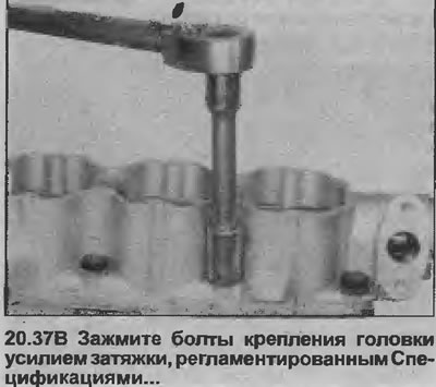
36. Install new head bolts, do not forget to install washers under the head, screw the bolts as far as possible by hand (see illustration).
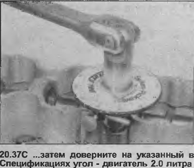
37. Tighten the bolts in a spiral from the inside out as shown (see illustration). Tighten the bolts in four stages - that is, tighten all the bolts with a Stage 1 torque, then tighten all the bolts with a Stage 2 torque, and so on (see illustrations).
38. Further installation is carried out in the reverse order of removal. Pay attention to the following.
39. Make sure that the high voltage wires are installed on their respective cylinders.
40. Install the camshaft sprocket and toothed drive belt, tension the belt as described in Chapter 11.
41. Where necessary, install manifolds on the cylinder head as described in Section 4A, 4B or 4C, use new gaskets.
42. Reconnect the outlet pipe to the manifold using a new gasket. To do this, follow Section 4C, if it is needed.
43. Install the alternator top mount, then adjust the alternator drive belt tension as described in Section 5.
44. Fill the cooling system as described in Section 3.
45. Finally, check that all relevant hoses, pipes, wires, etc. are connected.
46. When the engine is started, check for signs of leaks
47. Once the engine has warmed up to normal operating temperature, check and, if necessary, adjust the idle speed (if it is possible) and mixture (if it is possible), as described in Sections 4A or 4B.
Visitor comments