
Removal and installation of a head of cylinders (engine not removed)
The cylinder head can be removed with the engine installed. This operation is briefly described below. It is also necessary to read the contents of the section describing the removal of the engine, since many of the work on removing the engine must also be done when removing the cylinder head. If the engine has already been removed, preparatory work may not be carried out.
Removal of the cylinder head without removing the engine is required, for example, when replacing the cylinder head gasket or for grinding valves. Cylinder heads may only be removed after the engine has cooled down (up to room temperature).
The removal of the cylinder head for different engine types is described separately. However, not all the differences that occur for different types of engine are described here.
OHC engine - type C20NE - up to 1995
Removing
1. Disconnect the ground cable from the battery.
2. Drain the liquid from the cooling system (Chapter Filling the cooling system cooler Chapters Ongoing care and maintenance) and disconnect the hoses from the thermostat housing. Collect coolant in a container for further use if it has been in the system for a short time.
3. Disconnect the exhaust pipe from the exhaust manifold.
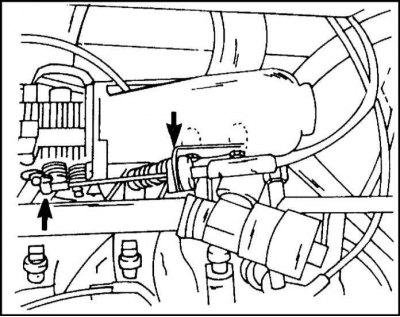
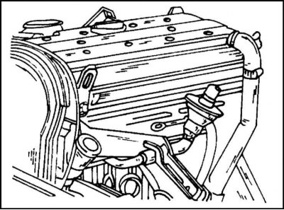
4. Disconnect the throttle cable from the articulated head and from the support. Its attachment is shown in Fig.
5. The cylinder head may be removed with the manifold, or the manifold may be detached from the cylinder head prior to removal. If, for example, only the cylinder head gasket needs to be replaced, the intake manifold can be detached from the cylinder head and moved to the side. In this way, the work of disconnecting various pipelines, cables and hoses can be saved.
6. If the cylinder head is to be removed with the exhaust manifold, all hoses, pipes, cables, etc. must be disconnected. from the exhaust manifold.
7. Remove the alternator drive belt.
8. Disconnect the air intake hose from the throttle body. Disconnect the hose from the camshaft bearing housing cover. This is a ventilation hose connected to the intake manifold.
9. Disconnect cables from spark plugs and ignition coil. Label the cables if necessary.
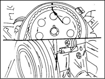
10. The following operation is important and must be performed before removing the toothed belt. Insert a socket wrench into the center of the crankshaft pulley and turn the crankshaft in the direction of rotation so that it and the camshaft are in the position shown in illustration. (camshaft - top, crankshaft - bottom). The mark on the camshaft wheel should align with the mark on the bar, the pin on the underside should be opposite the crankshaft mark.
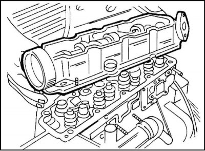
11. Remove the camshaft housing cover.
12. Remove the toothed belt. This work is described in the corresponding section.
While holding the camshaft sprocket from turning, remove the bolt in the center. Remove the wheel. Loosen the upper bolts of the rear belt guard.
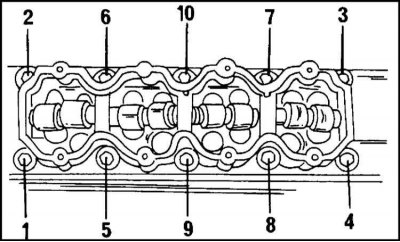
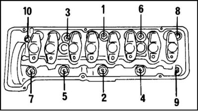
13. Turn away bolts of fastening of a head of cylinders for some receptions in the sequence shown on an illustration. For the first step, unscrew the bolts no more than a quarter of a turn, for the second step, half a turn. Use a socket wrench to unscrew.
14a. Remove the camshaft bearing housing from the cylinder head. The operation is shown in fig. 6.14a. If necessary, a rubber mallet can be used to pry off the housing. Note that the housing has guide pins.
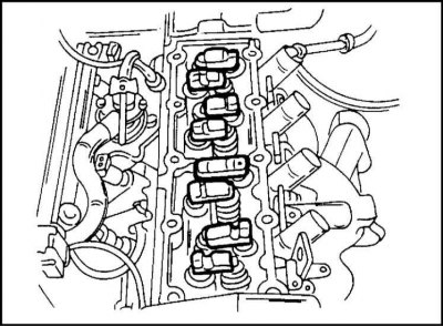
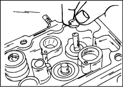
14b. Rocker arms, pressure elements and hydraulic pushers (valve clearance compensators) take out in order and mark. Keep the details of one node together. The location of the parts before removal is shown in illustration. 6.14b. Pushers must be placed in a vertical container filled with oil to prevent air from entering the internal cavities.
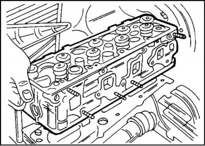
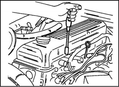
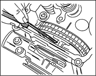
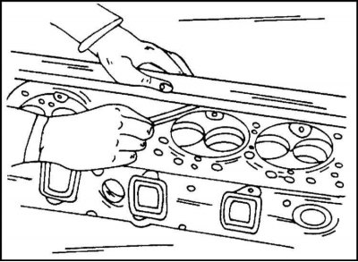
15. Remove the cylinder head and remove the gasket. A firmly seated cylinder head can be tapped with a rubber mallet. Do not separate the cylinder head from the cylinder block with a screwdriver. The capture of the cylinder head during removal is shown in illustration.
Thoroughly clean the surfaces of the cylinder head and cylinder block and check the flatness of their surfaces with a steel ruler as described below.
The cylinder head bolt holes must be free of oil, which can form hydraulic cushions.
Installation
The cylinder head is installed as follows:
1. Place a gasket on the cylinder head so that the OBEN/TOP lettering is at the top and on the drive side of the timing mechanism.
2. Install the cylinder head on the cylinder block and tap it with a rubber mallet. The guide bushings must fit into the appropriate holes.
3. Install hydraulic pushers, pressure elements and rocker arms. Lubricate the parts with a small amount of graphite grease. Parts must be installed in their original places.
4. Lubricate the mating surface of the cylinder head with sealant.
5. Install the camshaft bearing housing to the cylinder head. Temporarily insert the camshaft wheel to make sure the mark is in the correct position.
6. Install new cylinder head bolts (they always need to be replaced) and tighten them all the way.
7. Tighten the bolts in the reverse order shown in fig.
8. The bolts must be tightened using the socket set already mentioned above, as follows: Tighten all bolts in sequence to 25 Nm.
9. Using a socket head, tighten each bolt 90°in the sequence shown (quarter turn) without using a torque wrench.
10. From this position, again tighten each bolt by 90°in the sequence shown.
11. Tighten all bolts again in sequence by 90°. Thus, turning by 90°is performed three times.
The above operation is performed as follows. The head is mounted on the bolt so that the handle is parallel to the cylinder head. After turning 90°, the handle should be in a position perpendicular to the longitudinal axis of the cylinder head. In specialized workshops, to maintain the tightening angle, a graduated washer is used, shown in fig.
12. Bolt the rear toothed belt guard (6 Nm) and put the wheel on the camshaft. While holding the wheel from turning, tighten its fastening bolt to 45 Nm.
13. Connect the exhaust manifold to the downpipe of the exhaust system.
14. Put on a toothed belt and tighten it. Details of this operation are described in the corresponding section.
15. All other work is performed in the reverse order of disassembly. Finally, tension the alternator drive belt and power steering pump.
OHC engine - type X20SE - since mid 1995
Removing
Removing the cylinder head on this engine is similar to removing the cylinder head on an older engine. However, there are some differences due to changes in engine design. Before removing the cylinder head, the engine must be cooled to room temperature. The cylinder head is removed as follows:
1. Disconnect the plug connection and disconnect the hoses from the inlet pipeline.
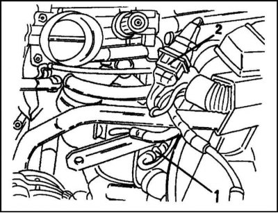
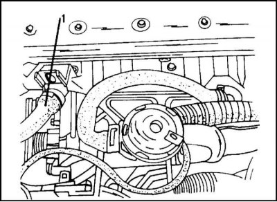
2. Disconnect both plug connections shown in fig. This is the connection of the coolant temperature sensors (1) and crankshaft position (2).
3. Drain the coolant from the system.
4. Disconnect the two coolant hoses from the thermostat housing.
5. Turn out bolts and remove a protective sheet of the pallet crankcase.

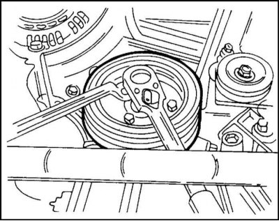
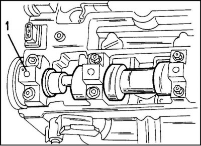
6. Remove the vibration damper from the front of the engine. To avoid turning the crankshaft, it is necessary to hold the central bolt when unscrewing the vibration damper mounting bolts, as shown in illustration.
7. Remove the front toothed belt guard.
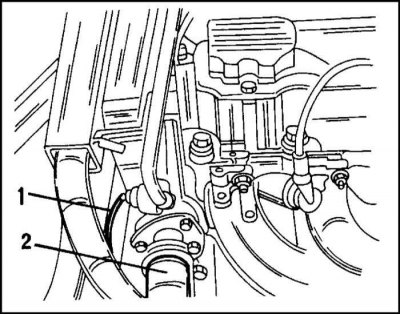
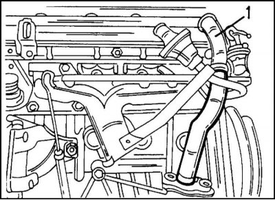
8. Disconnect the plug connection of the coolant temperature sensor (1) and disconnect the upper coolant hose (2) from the outlet. Connection locations are shown in fig.
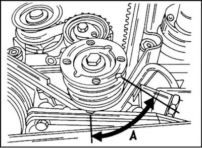
9. The following operation must be performed before removing the toothed belt. Insert the socket into the center of the crankshaft pulley and turn it in the direction of rotation so that the shaft is in the position shown in illustration. Corner "A" should be 60°.
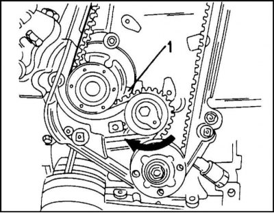
10. Now remove the toothed belt. To do this, loosen the tension roller mounting bolt and turn the adjusting eccentric in the direction of the arrow (clockwise) so that the pointer (1) on illustration was opposite the left stop. Now carefully separate the toothed belt from the camshaft gear.
11. Disconnect the cable connection from the cylinder head cover.
12. Disconnect the three crankcase ventilation hoses from the camshaft housing cover, two of them are located on the same side (on the cable side), and one is on the opposite side.
13. Turn away bolts of fastening and disconnect a cover of the case of bearings of a camshaft.
14. While holding the gear wheel from turning, unscrew the bolt in the center. Remove the gear.
15. Remove two bolts from the end of the camshaft housing.
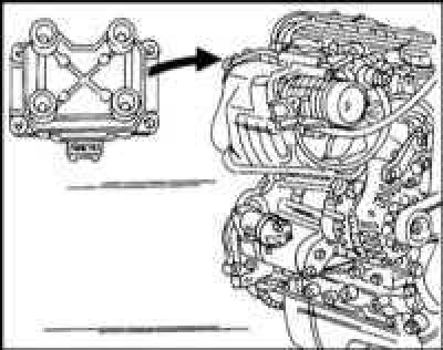
16. Loosen the mounting bolts and remove the load-handling bracket (engine transportation) from the camshaft bearing housing.
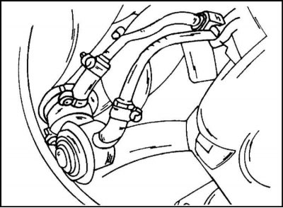
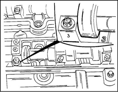
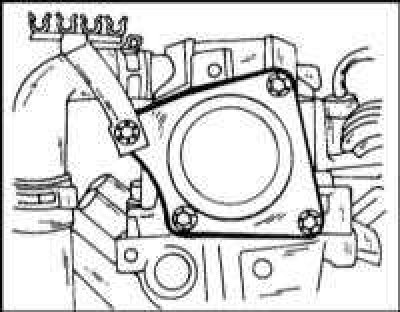
17. Turn away bolts of fastening and disconnect a reception pipe with catalytic converter from an exhaust manifold. The node in question is shown in Fig. 3.20

18. Turn away for several receptions bolts of fastening of a head of cylinders in the sequence shown on an illustration. For the first premium, the bolts are turned away no more than a quarter of a turn. The key is used for this "Torx 55".

19. Remove the camshaft bearing housing from the cylinder head. If necessary, a rubber mallet can be used to pry off the housing. In order, remove the rocker arms, pressure elements and hydraulic pushers and mark them. Store parts that belong to the same cylinder together. The location of the parts in question before removal is shown in illustration.
20. Remove the cylinder head and remove the gasket. A firmly seated cylinder head can be tapped with a rubber mallet. Do not separate the head from the cylinder block with a screwdriver.
Thoroughly clean the mating surfaces of the head and cylinder block and check their flatness with a steel ruler as follows. The cylinder head bolt holes must not contain oil, which can form hydraulic cushions.
Installation
The cylinder head is installed as follows:
1. Place a gasket on the cylinder head so that the OBEN/TOP lettering is at the top and on the drive side of the timing mechanism.
2. Install the cylinder head on the cylinder block and tap it with a rubber mallet. The guide bushings must fit into the appropriate holes.
3. Install hydraulic pushers, pressure elements and rocker arms. Lubricate the parts with a small amount of graphite grease. Parts must be installed in their original places.
4. Lubricate the mating surface of the cylinder head with sealant.
5. Install the camshaft bearing housing to the cylinder head.
6. Install new cylinder head bolts (they always need to be replaced) and tighten them all the way.
7. Tighten the bolts in the reverse order shown in fig. The bolts must be tightened using the set of sockets already mentioned above, as follows:
8. Tighten all bolts in sequence to 25 Nm.
9. Using a socket head, tighten each bolt 90°in the sequence shown (quarter turn) without using a torque wrench.
10. From this position, again tighten each bolt by 90°in the sequence shown.
11. Re-tighten all bolts in sequence by 90°. Thus, the rotation through an angle of 90°is performed three times.
The above angle of rotation of the bolts is achieved as follows. The head is mounted on the bolt so that its handle is parallel to the cylinder head. After turning 90°, the handle should be in a position perpendicular to the longitudinal axis of the cylinder head. In car repair shops, a graduated scale is used to maintain the tightening angle, shown in fig.
12. Bolt the rear toothed belt guard (6 Nm) and put the gear on the camshaft. While holding the wheel from turning, tighten its fastening bolt to 45 Nm.
13. Bolt the lifting eyes (15 Nm).
14. Connect the muffler downpipe to the exhaust manifold.
15. Put on and tension a toothed belt.
16. All other work is performed in the reverse order of disassembly. Finally, tension the alternator drive belt and power steering pump. Tighten the vibration damper mounting bolts to 20 Nm while holding the crankshaft from turning.
Engine OHC 2.4 l (C24NE) (with chain drive distribution mechanism)
Removing
The cylinder head can only be removed when the engine is cold, i.e. at an oil temperature not exceeding 20°C.
1. Disconnect the ground cable from the battery.
2. Disconnect the muffler downpipe from the exhaust manifold. To do this, use a head with an extension cord.
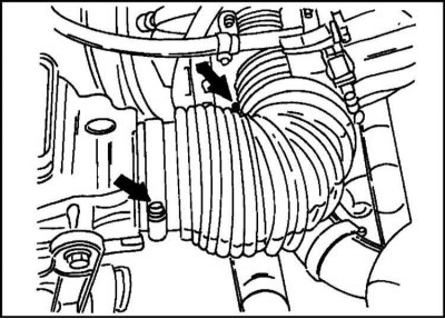
3. Loosen both clamps, shown by arrows in fig. and remove the air intake hose.
4. Drain the liquid from the cooling system.
5. Disconnect all hoses from thermostat housing and coolant pump.
6. Disconnect the throttle cable.
7. Disconnect the plug connection of the injection valves and the throttle valve potentiometer.
8. Disconnect the mass cable from the intake manifold by unscrewing the screw.
9. Mark both fuel hoses according to fig. and remove by loosening the clamps. Be careful - fuel may be under pressure.
10. Disconnect the camshaft housing ventilation tube from the intake manifold.
11. Remove the cylinder head cover as shown in the illustration by removing the bolts. Under the cover is the camshaft. Disconnect the plug-in connections of the spark plugs in order, having previously marked them.
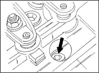
12. Set the #1 cylinder piston to TDC. For this type of engine, this must be done exactly. The recess in the camshaft must be in the position shown in illustration. In addition, there is a ball in the flywheel, which should be opposite the pin in the cylinder block.
13. Remove the front protective cover from the cylinder head.
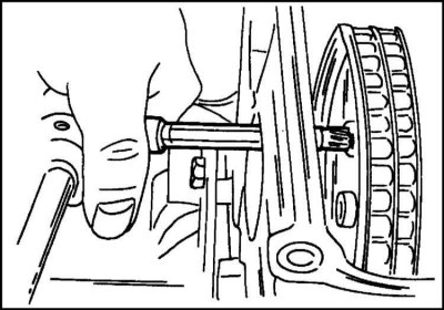
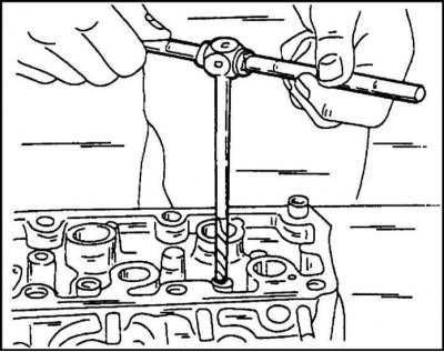
14. Unscrew the plastic fuel limit screw from the camshaft and remove the gear wheel, holding the camshaft from turning. This requires a multi-slotted key, which is inserted as shown in the illustration.
15. Turn both screws inserted at the top left and right outwards. The screws secure the control unit to the cylinder head.
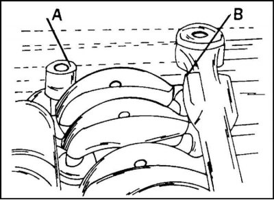
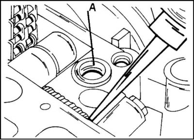
16. Turn away bolts of fastening of a head of cylinders evenly on a spiral outside inside. First a quarter turn, then a half turn. Use a sturdy Allen wrench to loosen the bolts. To unscrew the two rear bolts, you must use a 10 mm hexagon of different lengths. Bolt (A = right side), shown in the illustration, is turned with a key, 73 mm long, bolt (B = left side) - with a key 103 mm long.
The use of wrenches of a different length may cause difficulty in loosening the bolts.
17. Remove the cylinder head from the block, being careful not to damage the throttle switch and the throttle itself.
18. Thoroughly clean the mating surfaces of the cylinder block and head. You can use a flat scraper for this. Carefully remove the remnants of the gasket.
Installation
The cylinder head is installed in the reverse order of its removal. In doing so, you need to pay attention to the following:
1. The mating planes of the bearing housing of the distribution mechanism and the cylinder block are covered with sealant. Opel uses sealant No. 1503294, sold in tubes, for this. The sealant is applied with a 3 mm wide roller at the location shown in fig. In this place there is a recess where the rubber sealing ring is inserted. Stuffing box (A) replace.
2. Install a new gasket and install the cylinder head, being careful not to. so that the guide bushings fit into the holes.
3. Install new cylinder head bolts in order and hand-tighten. Tighten the bolts in the sequence shown in fig. Pay attention to the tightening of the two rear bolts (see instruction below):
- tighten all bolts shown in the illustration to a torque of 60 Nm;
- all bolts shown in fig. tightened without the use of a torque wrench at an angle of 90° (quarter turn).
Cylinder head rear bolts: Due to the design, the rear bolts cannot be tightened immediately by 90°. First, one bolt is tightened at an angle of 30°, then the other. Socket wrenches of different lengths should be used.
4. Install the timing cover on the cylinder head (tightening torque 25 Nm).

5. Check that the markings on the camshaft sprocket and camshaft bracket match, and the ball on the flywheel is against the pin in the cylinder block. Fasten the camshaft gear with a torque of 25 Nm (see illustration.).
6. Install a new plastic fuel limit screw.
7. Next, you need to measure the gap between the thrust surfaces of the cover and the stop screw. To do this, insert the probe in the place indicated in the illustration. If the gap is outside 0.1 - 0.2 mm, the cover must be removed again and adjusted by striking the thrust surface with a blunt mandrel.
8. Check that the mating surfaces are well cleaned and install a new gasket under the cylinder head cover. Opel workshops use for sealing "Pattex". Long bolts are installed under the bracket.
9. Connect the spark plug connectors.
10. Connect the crankcase ventilation hose to the intake manifold.
11. Connect the fuel lines as marked.
12. Connect the mass cable to the inlet pipeline.
13. Dock all plug connections, attach the throttle cable and vacuum hoses.

14. Other work is carried out in the reverse order of disassembly. The bolts connecting the exhaust pipe of the muffler and the exhaust manifold must be lubricated with graphite grease. The air suction hose is connected according to fig.
DOHC engine
Removing
Allow cylinder head to cool to room temperature before removing.
1. Disconnect the ground cable from the battery.
2. Drain the liquid from the cooling system as described in Section Filling the cooling system cooler Chapters Ongoing care and maintenance. The coolant can be collected in a container and reused if it has not been used for too long.
3. Disconnect all plug connections and disconnect the hoses from the intake manifold.
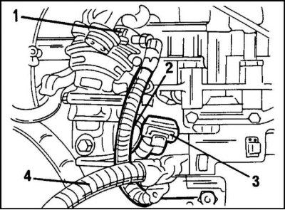
4. Disconnect the plug connections shown in fig. Plug (1) belongs to the EGR system (exhaust gas recirculation), plug (2) belongs to coolant temperature gauge sensor, plug (3) also belongs to the sensor (another) coolant temperature. cable harness (4) disconnect from the clamp and take it aside.
5. Disconnect the other two plug connections. One plug belongs to the ignition module, the other to the adsorber control valve. The latter is also called the evaporator valve.
6. Disconnect the coolant hose from the adapter on the ignition module.
7. Raise and place the front of the vehicle on stands. Loosen the bolts and remove the sump shield from the chassis.
8. Remove the vibration damper from the front of the engine. To prevent the crankshaft from turning, hold the center bolt when loosening the damper mounting bolts.
9. Turn away bolts and disconnect a reception pipe from a final collector.
Remove the spark plug cable cover from the cylinder head cover.
10. On the drive side of the timing mechanism, approximately in the center of the toothed belt, disconnect the plug connection (camshaft position sensor).
11. Loosen the screws and remove the cable cover from the toothed belt protection cover, move the cables aside and, having unscrewed all the bolts, remove the protection cover.

12. Now remove the toothed belt. To do this, loosen the tension roller mounting bolt and turn the adjusting eccentric in the direction of the arrow (clockwise) so that the pointer (1) on illustration was opposite the left (same for OHC and DOHC engines). Now carefully remove the toothed belt from the camshaft wheel.
13. Disconnect the two coolant hoses from the fittings.
14. Disconnect the upper coolant hose from the thermostat housing. Hose (1) shown in illustration.
15. Disconnect the air hose from the secondary air check valve. New engines do not have this system.
16. Disconnect and remove the ventilation hose (1) on illustration
17. Disconnect the spark plug connectors. There is a special tool for this.
Remove the cylinder head cover. Pay attention to the presence of the sealing ring.
18. While holding both camshaft gears from turning with a wrench on the camshaft hex, remove the wheel bolts. Remove both gears. Turn out also the sensor of position of a camshaft located in the middle between both camshafts.
19. Loosen 5 bolts (two down, three up) and remove the engine cover.
20. Before removing the camshaft bearing caps, you need to pay attention to the digital marking of the caps, which will help you later install them in their original places. Loosen the nuts securing the covers in several steps crosswise (each reception from half a turn to one turn) so that they turn freely. In order, remove the covers and take out the camshafts. There is a thrust bearing in front.
Remove the oil seal from the camshaft. The location of the markings of the covers is shown in illustration.
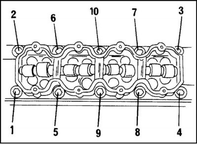
21. Turn away bolts of fastening of a head of cylinders for some receptions in the sequence shown on an illustration. For the first reception, the bolts are turned away at an angle not exceeding a quarter of a turn. Bolts are unscrewed with a socket wrench "Torx 55". On illustration. an eight-valve engine is shown, but the bolt arrangements for the engine in question are similar.
22. Remove the cylinder head and remove the gasket. A firmly seated cylinder head can be tapped with a rubber mallet. Do not separate the cylinder head from the cylinder block with a screwdriver.
Thoroughly clean the cylinder head and block surfaces and check their flatness with a steel ruler as described below. The cylinder head bolt holes must not contain oil, which can form hydraulic cushions.
Installation
The cylinder head is installed as follows:
1. Place a gasket on the cylinder head so that the inscription "OBEN/TOP" was at the top and from the drive side of the distribution mechanism.
2. Install the cylinder head on the cylinder block and tap it with a rubber mallet. The guide bushings must fit into the appropriate holes.
3. Install new cylinder head bolts (they always need to be replaced) and tighten until tight.

4. Tighten the bolts in the reverse order shown in fig. The bolts must be tightened using the set of sockets already mentioned above, as follows:
- tighten all bolts in sequence to 25 Nm;
- turn each bolt 90°in sequence using a socket head (quarter turn) without the use of a torque wrench;
- from this position again tighten each bolt by 90°again in the indicated sequence;
- Tighten all bolts again in sequence by 90°. Thus, a 90°rotation is performed three times.
The above angle of rotation of the bolts is achieved as follows. The head is mounted on the bolt so that its handle is parallel to the cylinder head. After turning through an angle of 90°, the handle should take a position perpendicular to the longitudinal axis of the cylinder head.
5. Lubricate the working surfaces of the hydraulic tappets and camshaft journals with graphite grease and lay the camshafts in the cylinder head.
6. Lubricate the mating surface of the front guide bearing with sealant (1) on illustration and install the bearing. Install the remaining bearing caps. Immediately check that the markings on the covers match the corresponding markings on the cylinder head (illustrations higher).
7. Tighten the cap nuts crosswise to 8 Nm.
8. Bolt the rear toothed belt guard. Screw in the camshaft position sensor (6 Nm).
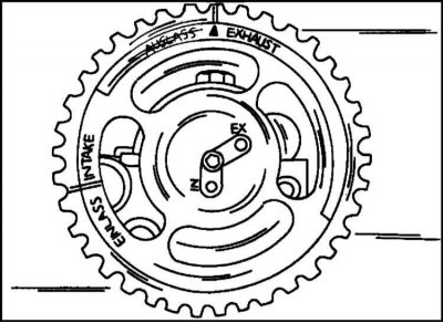
9. Slide the gears onto the camshafts with the marks facing out. The position of the gears is shown in fig. Marking visible in the center "EX" And "IN". Put on the gears so that the intake camshaft wheel enters the hole marked "EX".
10. Insert the bolts and, holding the camshaft with a wrench by the hex, tighten them. First with a torque of 50 Nm, then from the position reached through an angle of 60°and finally again by 15°.
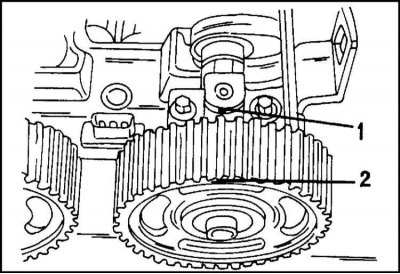
11. Turn the camshafts so that the mark on the gear (2) stood opposite the spout on the front bearing cap (1). Rotate the crankshaft in the direction of rotation (head on the central bolt of the gear) so that the marking on the crankshaft wheel is opposite the mark on the cylinder block. After that, put on the timing belt and tighten it as described in the appropriate section for the DOHC engine.
12. Install the cylinder head cover with new O-rings.
13. Other work is performed in the reverse order of disassembly. When assembling, observe the following tightening torques: vibration damper 20 Nm, crankcase breather flange (new gasket) 25 Nm, front and rear toothed belt guards 8 Nm, spark plug caps 3 Nm.
Dismantling and assembly of a head of cylinders
Due to the fact that the design of the cylinder head depends on the type of engine, the description of the assembly and disassembly of the cylinder head is given separately for each type of engine. The following is a description of the disassembly and assembly of the cylinder head, whether it has been repaired or not.
OHC engine - timing belt drive
Disassembly
1. Take out the hydraulic pushers and put them in the order of installation.
2. In the prescribed sequence, disconnect the coolant pipe, thermostat housing, ignition module holder, spark plugs from the cylinder head (special key), heat shield, exhaust manifold and intake manifold.
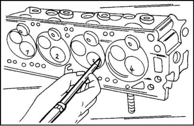
3. Valve discs are marked (scriber marks), as shown in the illustration, which allows them to be reinstalled when reassembling.
4. To remove the valves, use a valve spring compressor. The device is installed not on the cylinder head, as shown in the illustration. Pressing the tool lever compresses the valve springs. After that crackers, springs, plates and valve stem seals can be removed. Next, the guide bushings are removed.
5. Carefully remove the oil seals with a screwdriver or pliers from the guide bushings. Under them are spring support washers, which can now be removed. Caps should be thrown away immediately (to be replaced).
Thoroughly clean all parts and, if required, check according to the requirements of subsection "Cylinder head repair".
Assembly
Assembly is done as follows:
1. Lubricate the valves with engine oil and insert into the guides (in accordance with the marking).

2. Put on valves and directing oil-slinger caps. To prevent damage to the caps, put protective plastic caps on the ends of the valve stems (illustrations).
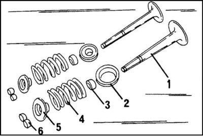
3. After installing the spring, distance rings (exhaust valves - 1), support washers (inlet valves -- 2), valve stem seals (3) and plates (5) compress the springs (4) and insert breadcrumbs (6). Lubricate the inner surfaces of the crackers with a thin layer of grease so that they stick. Slowly release the spring, making sure that the cotters are properly seated.
The cylinder head is assembled in the reverse order of its disassembly. The following tightening torques must be observed: (Look Specifications).
4a. OHC engine hose routing since mid 1995 release.
4b. Since the middle of 1995, the OHC engine has been fitted with a cover with a cardboard gasket on the camshaft bearing housing.
5. Finally, lubricate the hydraulic tappets with oil and insert them into the corresponding holes in the cylinder head. Do not swap pushrods.
Notes for OHC motor with timing belt drive
For older engines "From 20 N.E" the exhaust valves have valve turning devices, and the exhaust valves have steel rings. Differences in the design of the valves can be seen in the illustration. higher. With the advent of the engine "X 20 SE" the valve turning devices were removed, and spacers were installed in their place.
In the new engine, the crankcase ventilation hose is not routed to the crankcase, but to the camshaft bearing cap. The hose routing is shown in fig. paragraph 4a. The ignition distributor installed on the old engine model has been replaced with an ignition module on the new engine. The camshaft bearing housing is closed with a cardboard gasket. This eliminates the use of a camshaft seal (illustrations paragraph 4b).
1. The new engine model has heat protection tubes to protect the plug connection of the spark plugs. Turnkey hexagonal candles were also used here "at 16". Pipes are removed with a special tool KM-834.
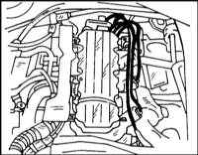
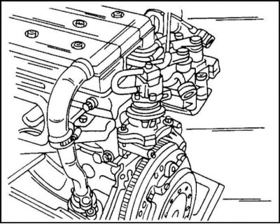
2. The ignition module mentioned above is located behind, to the right of the engine in the place shown in illustration.
OHC Engine - Chain Timing
Disassembly
1. Turn away bolts of fastening and remove the inlet pipeline, a final collector and the case of the thermostat.
2. Remove rockers and pushers. Turn away bolts and remove both covers, back and lateral.
3. Carefully remove the camshaft from the bearings without hitting the cams and necks on the working surfaces of the bearings.
Indication
The camshaft of the engine in question is marked on the end surface "U". In addition, the camshaft has a two-tone blue/brown marking. The camshaft with a purple marking is a repair one, in which the diameter of the necks is reduced by 0.10 mm.
4. Take out the valves as described earlier and arrange them in the order of installation.
5. Remove the oil seals with pliers.
6. Remove spark plugs.
Assembly
The cylinder head is assembled as follows:
1. Slide the new valve stem seals onto the valve guides (see illus.) and press them with a piece of pipe.
2. Lubricate the valve stem seals, guides and valve stems liberally with oil and reinstall. Install the valves in their places in accordance with the marking or, if they have been ground, in the appropriate guides. Inlet valves have threaded elements, exhaust valves do not.
3. Liberally lubricate the camshaft journals with oil and insert the shaft from the front into the cylinder head and support it through the mounting holes.
4. Install rockers and pushers.
5. Reinstall other removed parts.
DOHC engine
Disassembly
1. Remove the coolant inlet flange and thermostat housing.
2. Turn away bolts and remove from a head of cylinders the holder of the module of ignition.
3. Remove the intake manifold and exhaust manifold, remove the mounting bolts and remove the lugs from the cylinder head. Also remove the lifting eye.
4. Remove the valves as described for the OHC engine. The same applies to the removal of the oil seals. Valves in the order of their installation on the cylinder heads, insert into a cardboard box, piercing its bottom. On the side of the box where the valves of the front of the engine are located, mark accordingly.
5. Remove the spring washers with pliers. Thoroughly clean all parts and check as described in subsection "Cylinder head repair". Replace parts if necessary.
The cylinder head is assembled in the reverse order of disassembly and in accordance with the description for the OHC engine. The following tightening torques must be observed: (see specs).
Finally, insert the hydraulic pushers into the appropriate holes (generously lubricate). Insert used pushers into their holes.
Note for DOHC engine from mid 1995
1. This type of engine from mid-1995 has an EGR valve and a fuel tank vent valve located on the back of the cylinder head, as shown in illustration.
2. This engine also has a secondary air supply system. Under certain operating conditions, the electric pump supplies additional air to the exhaust manifold to reduce the content of harmful substances in the exhaust gases. This also increases the temperature of the exhaust gases, which in turn increases the efficiency of the catalytic converter.
Before removing the cylinder head, the parts of the secondary air supply system must be removed from the exhaust manifold. The O-ring must be replaced on the air supply pipe before it is installed on the exhaust manifold. The arrangement of the parts mentioned above is shown in fig. The ignition module is located at the rear, on the right side of the cylinder head, as shown in illustration. higher.
Recommendation for the repair of engines of all types
To remove the valves, a piece of pipe installed on the upper spring plate can be used. The bottom support washer must be well supported. Apply a sharp blow to the piece of pipe with a hammer so that crackers pop out. They must remain inside the pipe. To prevent crackers from flying off to the side, the pipe must have good contact with the plate.
Cylinder head repair
The instructions below apply to the OHC engine. For differences regarding other engines, instructions are given at the end of the section.
Valve springs
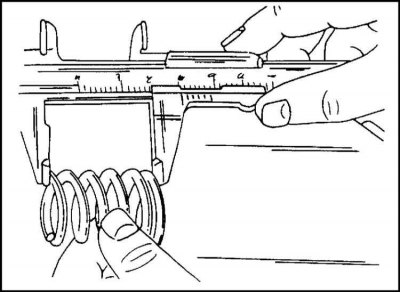
The length of the spring changes in the free state, as shown in the illustration. All springs must be the same length.
A special tool must be used to control the spring force. In its absence, proceed as follows:
1. Compare the used spring with the new one. To do this, the springs are attached one to the other and clamped in a vice. If the springs are deformed by the same amount, then this indicates their approximately equal stiffness.
2. If a used spring compresses more than a new one, this indicates that the spring is fatigued and should be replaced as a set.
3. Install the springs in order on a level surface (e.g. on glass) closed loop down. Place a steel square next to the spring. The gap between the spring and the square must not exceed 2.0 mm. A large amount of clearance indicates a deformation of the spring. In this case, the spring is replaced.
Valve guides
1. Clean the guide bushings with a cloth soaked in gasoline. Also clean the valve stems. After that, insert the valves into their guides.
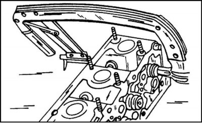
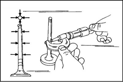
2. Install on the cylinder head on the indicator holder (illustrations). Slide the valve out of the guide until its end is flush with the edge of the guide on the other side of the cylinder head by moving the valve poppet back and forth in the direction of the arrow.
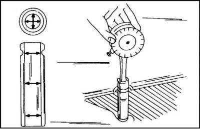
3a. Move the valve disc by hand and read the indicator. If the indicator shows a deviation of more than 1.0 mm at the inlet and more than 1.3 mm at the exhaust valve, then in most cases this indicates the need to replace the guide. More accurate results are obtained by measuring the inner diameter of the guide and the outer diameter of the valve stem with a micrometer, as shown, respectively, in illustration. 3a and 3b in several sections and directions.
The measurement locations are shown on the left.
3b. The difference between the largest value of the sleeve diameter and the smallest values of the diameter of the rod gives the gap in the mating. When replacing guide bushings, keep the following in mind:
4. Oversized valves may be fitted to the engine during assembly at the factory.
5. Guide sleeves and valves are marked. Parts with minimum dimensions are not marked, parts that come as spare parts are marked "TO". Other markings mean the following (in brackets designation of spare guides):
6. Guide bushings can be deployed to the next repair size. In this case, the corresponding marking is applied to the guide. Guides are deployed from above (illustrations).
7. Check the general condition of the cylinder head before replacing the guide.
8. The guide is pressed out of the cylinder head from the side of the combustion chamber using a mandrel. The mandrel must have a groove at the end, with a diameter equal to the inner diameter of the guide.
9. If the guides are replaced, the valves must also be replaced. After that, it is necessary to grind the valve seats.
Lubricate the new guides liberally and press them from the camshaft side into the cold cylinder head.
10. Expand the guides after pressing with a special reamer. If such a sweep is not available, an adjustable sweep can be used. It is necessary to unfold the guides taking into account the clearance given in Specifications. If the guide is being replaced, the valve seats must be milled. Therefore, you must first read the instructions given in subsection "valve seats".
Valve seats
The valve seats are controlled using a special gauge. Due to the complexity of the work in question, it is recommended to hand over the cylinder head for repair to a car repair shop.
1. Check all seats for signs of wear and any damage. Small wear marks can be removed with a 45°cutter. If the seats have significant wear, they must be milled. Note that the seats must not cut too deep into the cylinder head. To do this, the valve is inserted into the hole and, on the other hand, the length of the protruding part of the valve stem is measured with a special gauge.
2. Seats must be milled if new guide bushings have been installed. This is done as follows:
- mill the seat at a 45°angle;
- slightly mill the upper edge of the seat at an angle of 15°and the lower edge at an angle of 60°so that the width of the working chamfer of the inlet valve seat is 1.0–1.5 mm, and the exhaust 1.7–2.2 mm.
If, as a result of milling the seats, the valve stem protrudes too far from the cylinder head, a measurement must be taken with new valves. If in this case the result is unsatisfactory, then it is necessary to change the cylinder head.
On an OHC engine, the valve seats cannot be replaced.
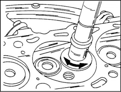
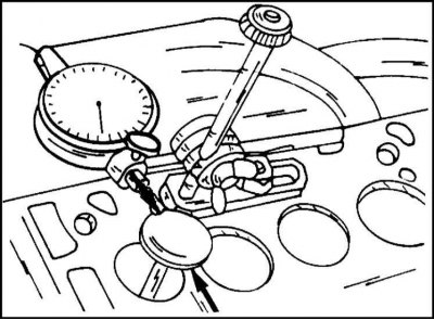
3. After milling the seats, they must be lapped. To do this, lapping paste is applied to the surface of the seat, and the valve is inserted into its seat. A suction cup is attached to the valve head and the valve rotates alternately in both directions (illustrations). Periodically, the valve should be lifted with a suction cup and turned a quarter of a turn.
4. After lapping, carefully clean all parts from dirt and paste and check the mating of the valve with the seat. The mating is satisfactory if, as a result of turning the valve, a continuous and clearly visible ring remains on the parts, the width of which is equal to the width of the mating surface.
5. Draw strokes with a pencil around the entire circumference of the valve face at a distance of approximately 1 mm from each other. Then carefully lower the valves into the hole in the guide bushing and rotate the valve 90°by pressing it lightly.
6. Remove the valve again and check if the pencil strokes have disappeared from the working chamfer of the valve plate. If the width of the working chamfer matches the specified one, the cylinder head can be installed in place. Otherwise, the saddles require processing. If it is impossible to achieve the specified values by machining the cylinder head, it must be replaced. You can get advice on repairing the cylinder head at a car repair shop.
Valves
Minor damage to the valve head face can be repaired by lapping as described above.
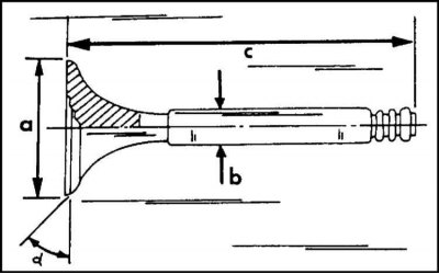
1. Measure the parameters of the valves indicated in the illustration (a = valve head diameter, b = valve stem diameter). In case of non-compliance with the specified values, replace the valves with new ones. Be aware of the differences between intake and exhaust valves. The required data is given in Specifications.
2. If the ends of the valve stems are worn, the valves are replaced as the stems are not ground.
3. The valve discs can be ground on a special grinding machine. However, this operation cannot be performed more than 1-2 times. As already mentioned, the protrusion of the valve on the back of the cylinder head must have a certain amount, which may change as a result of grinding the valve disc.
Damaged valves can be repaired by lapping. If this cannot be achieved, the valve is replaced. It is necessary to measure the diameters of the valve stems and the holes of the guide bushings and, based on the result, draw a conclusion about the advisability of further work with the cylinder head.
Cylinder head
1. Thoroughly clean the mating surfaces of the cylinder head and block. Check the surface of the cylinder head for flatness. To do this, lay a steel ruler on the surface as shown in the illustration, and check the gap between the ruler and the surface of the cylinder head with a feeler gauge. If the feeler gauge passes more than 0.10 mm into the gap, the cylinder head must be ground.
2. If the clearance is even greater, the cylinder head must be replaced.
The cylinder head can be ground until its height has become the minimum allowable (see specs). Otherwise, the cylinder head must be replaced. The need to maintain a certain amount of valve protrusion above the cylinder head should also be taken into account.
Camshaft
Work related to the camshaft is described in subsection "Gas distribution mechanism".
Cylinder head assembly
The cylinder head is assembled in accordance with those already given above in the section "Dismantling and assembly of a head of cylinders" instructions according to the type of engine.
Only for 2.4L engine
1. Valves can be ground 1-2 times to restore functionality (car workshop work). Make sure that the width of the working chamfers of the valve heads does not go beyond the set values.
2. As described above, the protrusion of the valve stem above the cylinder head must have a certain amount. A special tool is used for measurement.
3. The angle of the chamfer of the valve disc is 44°, the angle of the chamfer of the valve seat is 45°. They should not be confused.
4. Guide bushings available in two repair sizes (diameters increased by 0.075 and 0.150 mm). The corresponding marking is applied on the right and left sides of the spark plug hole.
5. The seat face width is 1.15–1.65 mm for intake valves and 1.5–2.0 mm for exhaust valves. The upper correction angle is 30°and the lower 75°.
6. The width of the working chamfer is 2.6–3.0 mm for the inlet and 3.7–4.1 mm for the exhaust valves.
7. The gap between the valve stem and the guide sleeve is 0.035–0.073 mm for the intake valves and 0.045–0.085 mm for the exhaust valves. Oversized valves are available. It should be borne in mind that oversized guides can be installed at the factory.
8. Check the flatness of the mating surface of the cylinder head as described above. Over a length of 150 mm, the gap should not exceed 0.015 mm. Over the entire maximum length, the nonflatness should not exceed 0.04 mm. As a result of grinding the cylinder head, its minimum height must not be less than 102.45 mm.
Valid for DOHC engine only
1. Compare the valve protrusion measurement data with the data given in Specifications. If the data is out of range, the cylinder head is replaced (first you need to insert new valves and measure the amount of protrusion with them).
2. For this type of motor, there are normal size guides and two repair guides with a diameter increased by 0.075 and 0.150 mm. The marking corresponds to the marking of the OHC engine.
3. The width of the working chamfer of the intake valve is 1.0–1.4 mm, the exhaust valve is 1.4–1.8 mm.
4. The height of the cylinder head between two mating planes for a DOHC engine is different (134.0 mm).
5. If the valve disc is ground on the machine, then it is necessary to maintain a chamfer angle of 44°40'.
6. The ends of the valve stems are not ground. However, they should not have any nicks.
7. Measure the valves according to the diagram in fig. 6.186 and compare the data obtained with the data Specifications. Too narrow working chamfers of the valves reduce the tightness of the combustion chamber.
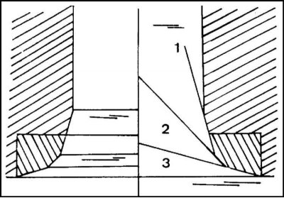
8. The angle of the working chamfer of the valve seat is 45° (2). Upper correction angle is 30° (1), bottom 60° (3). The layout of the corners is shown in fig.
Visitor comments