


Contents: Removal ⬇ Measuring the diameter of cylinders ⬇ Checking pistons and connecting rods ⬇ Measuring clearance in connecting…⬇ Assembly of the connecting rod and…⬇ Installation of connecting rod and…⬇
Removal
OHC engine
Pistons and connecting rods can be removed without removing the engine, for example to replace a piston or connecting rod bearing. In this case, it is necessary to remove the cylinder head and oil pan, as described in the relevant section.
Loosen the bolts and remove the oil pump suction pipe and oil baffle plate. If more extensive repairs are required, the engine must be removed.
The pistons and connecting rods are pushed upwards with the handle of the hammer. After this, the connecting rod bearing caps and liners can be removed. Before carrying out the above work, please read the following instructions regarding markings, installation directions and other features:
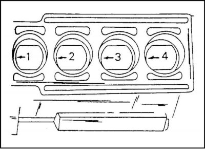
1. Each connecting rod and piston group must have markings for the corresponding cylinder. It is best to apply it with paint to the piston bottom (illustration). Here you also need to apply an arrow pointing to the front of the engine. The piston crowns are marked. However, due to carbon deposits they may not be visible. In addition, they can be damaged during the carbon removal process.
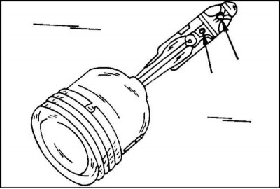
2. When removing the piston with the connecting rod, it is necessary to pay attention to the direction of installation of the connecting rod bearing cap. Before removing the cover, it is necessary to mark the connecting rod and cover with the cylinder number on one side (illustration). This is best done with a center punch (cylinder No. 1 with one punch, cylinder No. 2 with two punches, etc.). The connecting rod and the connecting rod bearing cover must be assembled in such a way that the protrusions on the connecting rods, shown by the arrows in the illustration, point towards the clutch, if the arrow or mark on the piston bottom points towards the timing mechanism drive.
3. The connecting rod bearing shells are marked according to the connecting rod and cap. Markings are applied with paint on the reverse sides of the upper and lower bearing shells.
4. If the piston has become disconnected from the connecting rod, then all assembly elements must be replaced - the piston, piston pin and connecting rod. The pistons are removed as follows. This means that the engine has been removed and the cylinder head, oil pan and oil pump inlet pipe have been removed:
5. Remove the bearing caps and take out the liners. Press the piston assemblies upward as described earlier. If necessary, use a scraper to remove carbon deposits from the top of the cylinders.
6. Check the piston group as described below on this page. If wear or any damage is detected, the entire group is replaced.
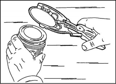
7a. If it is necessary to replace only the piston rings, they are removed with special pliers in order through the piston bottom. The pliers are installed on the piston ring as shown in the illustration. 7a, and the ring is moved apart until it comes out of the groove. If the rings are to be reused, they must be marked.
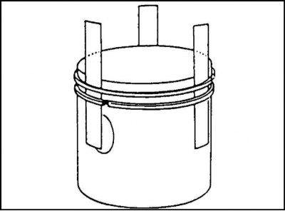
7b. If there are no special pliers for removing rings, then steel strips can be placed under the rings, as shown in the illustration. 7b. One strip must be installed under the end of the ring to prevent damage to the piston. The assembly of pistons and connecting rods for different types of engines is described separately.
2.0L OHC engine since mid-1995
The crank mechanism of this engine is completely taken from the previous engine. Therefore, the above description is true for this engine.
Engine 2.4L OHC
The work is carried out similarly to the above-described diagram, including marking the bottom of the pistons, connecting rods, etc. The arrow or mark on the bottom of the piston should face forward. The protrusion on the connecting rod should face backwards. The piston pin is held in place by retaining rings.
DOHC Engine
The instructions given for the OHC engine also apply to the DOHC engine when it comes to removal. There are differences when disassembling the connecting rod and piston group, since in this case the parts of the group can be replaced independently of each other. It is also worth paying attention to the design of the engine oil pan up to the end of 1997 and later. Details are described in the relevant section.
1. Mark each connecting rod and piston group when assembled. There is a machined boss in the middle of the connecting rod cap. The tip of this boss should point towards the flywheel.

2. Press out the piston pin, having first removed the retaining rings. The recess in the area of the pin hole allows the use of a mandrel to remove the retaining rings, as shown in the illustration. The pin is pressed out using the appropriate mandrel. Be careful not to damage the pistons. If necessary, the piston can be heated slightly.
3. The piston rings are removed as described above (ill. 7a). Store the rings in the order they were installed on the piston if they are to be reinstalled in the future. Before installing the piston ring they must be checked. At the same time, the clearances in height between the piston rings and grooves and the clearances in the lock are checked. If a new piston is installed, new piston rings must also be installed.
Measuring the diameter of cylinders
These instructions apply to all types of engines.
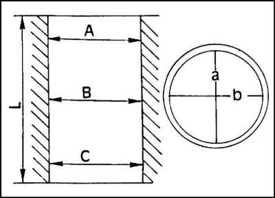
The diameter of the cylinders is measured with a micrometer bore gauge in three zones and in two directions (illustration). The upper and lower zones are located 10 mm below the upper and lower edges of the cylinder, respectively. In total, 6 measurements are performed for each cylinder. The obtained values should be recorded and compared with the values given in Specifications. It is necessary to keep in mind the difference in values for different types of engines.
If the diameter values of one of the cylinders go beyond the specified limits, then all engine cylinders must be bored. A deviation of 0.04 mm from the specified diameter value is acceptable. IN Specifications the diameters of the repair cylinders are given.
The bore diameter of a cylinder is defined as the sum of the piston diameter measured in cross-section at a right angle to the bottom and the clearance at the junction of the piston and the cylinder. In addition, it is necessary to take into account the 0.02 mm allowance left for honing. The operation in question must, of course, be performed in a specialized auto repair shop. Its description is given here for information purposes only.
To check the clearance in the piston-cylinder connection, their diameters are measured as described above. The difference in diameters represents the gap. If it goes beyond the permissible limits, the cylinders must be ground.
Checking pistons and connecting rods
Check all details carefully. If there are any burrs, deep scratches or signs of wear, the parts are replaced. The parts in question are subject to the following check:
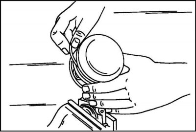
1. Measure the height clearances between the piston rings and grooves with a feeler gauge by inserting the rings into the corresponding grooves (illustration). If the specified clearance value is exceeded, the piston ring or piston is worn.
2. Insert all rings into the cylinder block in order. Using the piston upside down, push the rings down 15 mm.
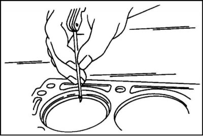
3. Use a feeler gauge to measure the gap in the ring lock (illustration). The ring is located under the lower edge of the cylinders. The measurement can also be taken from the bottom side of the cylinder. Compare the obtained values with the data in Specifications. Gaps must not exceed the wear limit.
4. If the gap is too small (for example, for new rings, where the gap must also be measured) the ends of the rings can be filed. To do this, a fine-cut file is clamped in a vice, and the rings are filed in this position. If the gap is too large, the ring must be replaced.
5. Check the piston pin and the bore for it in the connecting rod for wear and scoring (only if the parts will be reused). If there are defects in one of the parts, both are replaced as a set.
6. Check the connecting rods for skew and non-parallelism of the connecting rod head axes in a special device.
7. Connecting rod bolts are always replaced. They are not used again.
Measuring clearance in connecting rod bearings
This operation is described below in the subsection "Checking the crankshaft components".
Assembly of the connecting rod and piston group
Engine 2.0L OHC
When replacing pistons, they are all installed to the same size.
1. Before assembling the connecting rod and piston group, the connecting rod head must be heated to a temperature of 280°C, for which you can use, for example, a kitchen stove with a thermostat. It is also advisable to have a color rod to control the heat.
Due to the above mentioned difficulties, it is recommended that the assembly of the connecting rod and piston group be carried out by an auto repair shop. If the engine is removed from the vehicle, it is also recommended to take the cylinder block to a workshop to ensure the correct pistons are selected.
Attention! If the piston pin could not be pressed in as described above the first time, or the direction of installation of the piston or connecting rod is mixed up, the connecting rod and piston group must be replaced. Of course, such a situation should be excluded.
It is also necessary to keep in mind that all connecting rods must be replaced as a set, since they are selected by weight only as a set.
Engine 2.4L OHC
In the engine under consideration, the piston pin is fixed with retaining rings. Therefore, the assembly in this case is carried out in the same way as for the DOHC engine (see below).
DOHC Engine
The piston with the connecting rod of this engine is easily assembled after heating the connecting rod head. It is necessary to ensure the correct orientation of the piston and connecting rod. The lugs on the connecting rod and bearing cap must be on the same side as the piston pin boss area.
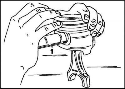
1. Generously lubricate the piston pin (1), insert the connecting rod into the piston and insert the pin through the piston and the connecting rod head. Holding the piston as shown in the illustration, push the pin in until it contacts the retaining ring on the opposite side. After this, install the second retaining ring. Check the reliability of the rings in the grooves.
For all engines
1. Using special pliers, install all piston rings in the grooves in order (see fig. 7a). Compression rings can be confused. Therefore, it is necessary to pay attention to their markings. The marking must be visible from the piston bottom side.
Installation of connecting rod and piston group
OHC engine
1. Generously lubricate the cylinder walls with oil.
2. Lay out the connecting rod and piston group in accordance with the markings and instructions given above.
Engine 2.0 l
1. The arrows on the bottom of the pistons should point towards the front of the engine.
Engine 2.4 l
1. On this engine the arrow or mark on the piston crown should point forward. The lug on the piston should point backwards.
The engine has 2.0 l
1. The compression ring locks must be positioned at an angle of 180° to each other. The oil scraper ring locks must be offset by 25-50 mm to the right and left relative to the lock of the middle compression ring. The locks are moved by turning the rings. The second ring has the marking "TOP" which should be visible from above after the ring is installed.
The engine has 2.4 liters
1. The top and bottom rings are marked "TOP". Both markings should face up. The oil scraper ring lock must be turned 180° relative to the compression ring.
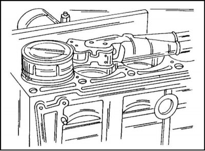
2. Place steel tape around the piston as shown in the illustration and press the rings into the piston. Check the reliability of the ring compression and the direction of piston installation.
3. Turn the crankshaft so that two of the connecting rod journals are at the bottom.
4. Insert the connecting rod into the cylinder from above. To do this, lay the engine on its side so that the connecting rod can be directed towards the crankshaft journal, and the cylinder walls and connecting rod bearing are not damaged. The connecting rod bearing shell must be located in the connecting rod and be inserted with the protrusion into the recess on the connecting rod.
5. Insert the piston into the cylinder so that the piston rings enter smoothly and the connecting rod heel sits on the crankshaft journal. Check immediately that the arrow on the piston bottom points in the direction of the distribution mechanism.

6. Insert the second bearing shell into the bearing cap, generously lubricating it. Place the lid on the insert and tap it lightly. Please note that the markings (illustrated) are facing the same direction.
7. Install and tighten new connecting rod bolts.
The engine has a 2.0L OHC
1. Tighten the connecting rod bolts alternately to 35 Nm. From this position, tighten the bolts by 45° and then by another 45°.
The engine has 2.4 liters
1. Tighten the connecting rod bolts on the left and right to a torque of 45 Nm.
All engines
1. After installing the connecting rod, turn the crankshaft several times and detect any resistance.
2. Install the other two connecting rod and piston assemblies in place by turning the crankshaft accordingly.
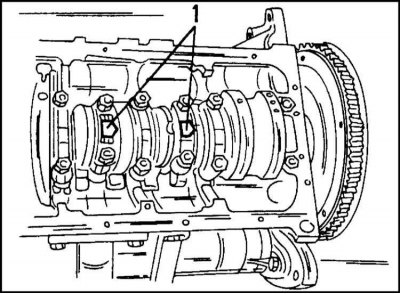
3. Recheck the markings on all connecting rods according to the illustration. The projections (1) on the connecting rod bearing caps must face the flywheel. Also check the direction of installation of the pistons (see illus. 1).
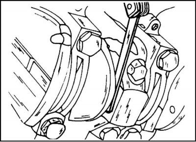
4. Measure the clearance between the side surfaces of the connecting rod and the crankshaft webs with a feeler gauge, as shown in the illustration. The axial clearance should not exceed 0.20-0.40 mm.
5. Apply sealant to the mating surfaces of the oil pump and the rear crankshaft bearing cover. Install a new oil deflector plate and tighten the mounting bolts.
6. Install the oil suction pipe onto the cylinder block. First tighten the bolts securing the pipe to the oil pump to a torque of 8 Nm (lubricate the threads with Loctite), then secure the holder to the cylinder block to a torque of 6 Nm.
7. Other assembly work is performed in the reverse order of disassembly, i.e. the oil pan, cylinder heads, etc. are installed.
DOHC Engine
The installation of connecting rod and piston groups on this engine is performed in the same way as on the OHC 2.0 l engine. The arrangement of piston rings is also similar here. Follow the instructions that apply to the 2.0L engine. This applies to the tightening torque of the connecting rod bolts.
The installation of the oil pan is carried out in accordance with the instructions given in the relevant section, since this operation has differences depending on the year of engine production. (before and after 1997.).
Visitor comments