
Note: When installing, use new connecting rod cap bolts.
Removing
1. Remove the cylinder head as described above in Chapter 20.
2. Remove the sump, oil pump pickup tube and sump deflector (where applicable), as described in Chapter 29.
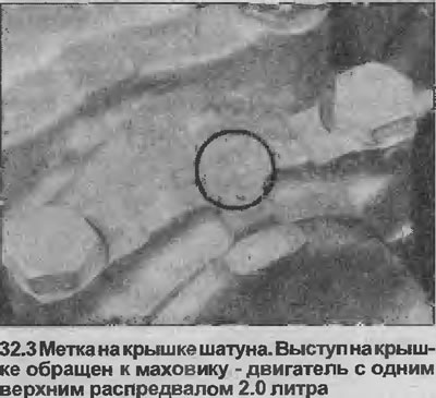
3. If the connecting rods and caps do not have marks indicating their position in the cylinder block (i.e. cylinder number), make marks yourself with a punch. Note the orientation of the marks in relation to the engine (see illustration).
4. Turn off bolts of a cover of the first rod, remove a cover. If the inserts are to be reused, tape the cap and insert together.
5. Check if there is a protrusion formed by wear at the top of the hole. If there is a protrusion, carefully remove it with a special tool, otherwise, after installing the piston, the piston rings may hit this wear ridge.
6. Use a wooden hammer handle to push the piston/connecting rod assembly up out of the cylinder bore. Remove the liner and tape it to the crank if you're going to reuse it.
7. Remove the remaining three assemblies in the same way. Rotate the crankshaft as needed to expose the connecting rod mounting bolts.
8. The piston can be separated from the connecting rod by removing the circlips that secure the floating piston pin. Note the orientation of the piston and connecting rod before separating, make marks if necessary. Assembly is carried out in the reverse order, but make sure that the piston and connecting rod are correctly oriented.
9. Pistons and connecting rods can be checked for signs of wear and damage as described in Chapter 33, and the bearings can be checked as described in Chapter 35.
Installation
10. Lay out the piston/connecting rod assemblies in their correct order, along with the liners, so that everything is ready for installation in the cylinder block.
11. Check that the earbud seats are absolutely clean, then reinstall the earbuds.
12. Wipe and lubricate the cylinder bores. Liberally lubricate the piston rings, check that the gaps of the ring cuts are located as described in Chapter 33.
13. Install the piston ring tool in the piston grooves on the first assembly to be installed.
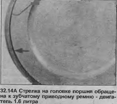
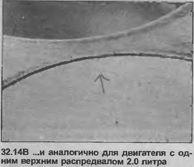
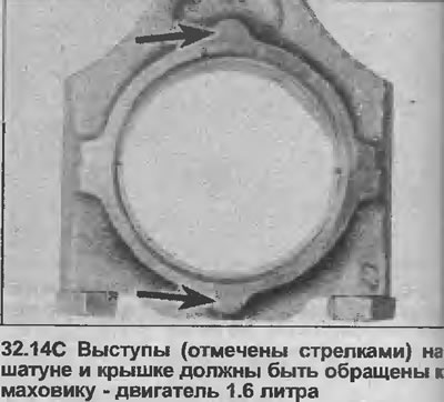
14. Insert the connecting rod with the piston through the top of the block into the bore of the cylinder so that the base of the swaging tool rests on the block. Check that the marks on the connecting rod are oriented as noted before removal. Note that the arrow or notch, depending on the model, on the piston head must face the toothed drive belt and the lugs on the connecting rods must face the flywheel (see illustrations).
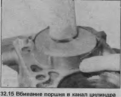
15. Hitting the piston head with a wooden hammer handle, hammer the assembly into the cylinder bore while releasing the compressor (see illustration).
16. Lubricate the corresponding connecting rod journal of the crankshaft, then position the lower head of the connecting rod on the neck. Make sure that the bushing does not fall out of the connecting rod.
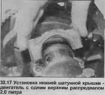
17. Install the connecting rod cap, orienting it as noted prior to removal (see illustration). Note that the tab must face the flywheel.
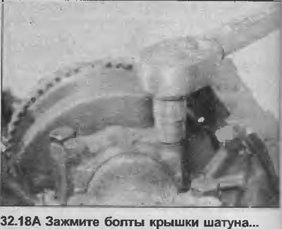
18. Install and in two stages tighten the new connecting rod cap bolts with the tightening torque specified specifications (see illustrations).

19. Repeat the procedure with the remaining three assemblies.
20. Install the pan deflector (where applicable), oil pump downpipe and sump as described in Chapter 29.
21. Install the cylinder head as described earlier in this Chapter 20.
Visitor comments