
2. On 2.0L engines, remove the cylinder head and bottom pan section. Unscrew the bolts of the upper section of the pan, unscrew the bolts securing the oil receiver to the balancing mechanism (or main bearing cap frame). Move the upper section of the sump to the front of the engine, unscrew the remaining mounting bolts and remove the oil receiver. Loosen the bolts and remove the oil deflector. Evenly and gradually unscrew the bolts of the balancing mechanism (or main bearing cap frame) and remove these nodes.
3. Check up existence of a shoulder in the top part of cylinders. The shoulder must be removed with a reamer or scraper without damaging the cylinder wall. The formation of a shoulder indicates increased wear on the cylinder.
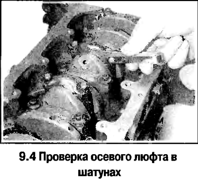
4. Use a feeler gauge to check the end play in the connecting rods (see photo). If the play exceeds the norm, then replace the connecting rods.
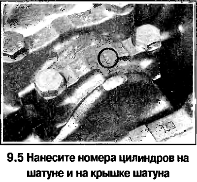
5. Paint or paint (see photo) on the polished surface of the connecting rod and cap cylinder number (if the engine was disassembled, then these marks should be found). Cylinder #1 is on the side of the camshaft belt.
5. Set the pistons of the 1st and 4th cylinders to the BDC position.
6. Turn away bolts of a rod cover of a rod of 1st cylinder. Remove the cover and remove the lower connecting rod bearing. If the liner is to be installed again, stick it with adhesive tape to the removed cover.
Attention! On parts of the engines, the split surfaces of the connecting rod caps and connecting rods are not polished, since the cover is processed together with the connecting rod both along the plane and to the diameter of the bearings, and then breaks off. On these engines, care should be taken to ensure that these surfaces are not affected during the disassembly-assembly process. Otherwise, premature wear of the connecting rod occurs.
7. Tape the threads of the connecting rod cap bolts. Use a hammer handle to push the piston into the cylinder and remove the piston through the top of the cylinder block. Remove the upper connecting rod bearing and tape it to the removed connecting rod.
8. Put the cover on the connecting rod and secure with nuts, without violating the previous order of assembly of parts.
9. Having repeated the specified operations, remove a rod with the piston of the 4th cylinder.
10. Similarly, remove the connecting rods with pistons from the 2nd and 3rd cylinders.
Visitor comments