OpelBook.ru
Cars AvtoVAZ Cars Mitsubishi Cars BMW Cars Mercedes Cars Nissan Cars Toyota Cars Chevrolet
English Русский
Български
Беларускі
Український
Српски
Hrvatski
Română
Polski
Slovenský
Magyar
 |  Sitemap  |  Contacts  |    


Main Astra Corsa Insignia Kadett Omega Vectra Zafira Others Articles
Astra F (1991-1998, petrol) Astra G (1998-2004, petrol) Astra G (1998-2004) Astra H (2004-2009) Astra J (2009-2015, petrol)
  • Main
  • Astra
  • Astra G
  • Power unit
  • Engine repair
  • Crankshaft — installation and checking clearances in main bearings

Crankshaft — installation and checking clearances in main bearings (Opel Astra G)

            0

Contents: Selection of main bearing shells ⬇ Checking clearances in main bearings ⬇ Engines 1.4, 1.6 and 1.8 l ⬇ Engine 2.0 l ⬇

Selection of main bearing shells


Attention! The manufacturer recommends changing the main bearings every time the engine is disassembled, regardless of their condition.


1. Both standard main bearings of various size groups and repair main bearings are supplied as spare parts. Bearings are selected based on the measured diameter of the main journal.

Checking clearances in main bearings


2. Clean the outer surface of the new main bearings, the surfaces of the bearing bores in the cylinder block and in the main bearing caps.

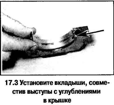
3. Insert the bearing shell, make sure that the protrusion on the bearing shell fits into the recess in the cylinder block bore or in the cover (see photo). The gap can be checked in two ways.
3. Insert the bearing shell, make sure that the protrusion on the bearing shell fits into the…


4. When determining the gap using the first method, install the covers (or the frame of the lids) main bearings together with the liners on the cylinder block, tighten the bolts to the specified torque and measure the inner diameter of each assembled pair of liners. The clearance in the main bearings is defined as the difference between the diameter of the corresponding main journal of the crankshaft and the inner diameter of the assembled bearing.


5. The second way (more accurate) consists of using plastic calibration wire.

6. After installing the main bearings in place, carefully install the crankshaft. The main journals must be dry and clean.

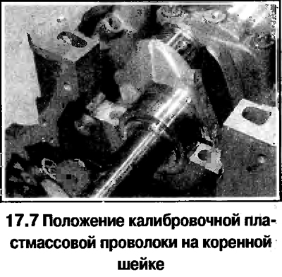
7. Place one piece of plastic calibration wire parallel to the crankshaft axis on each main journal "Plastigage", the length of which is slightly less than the width of the main bearings (see photo).
7. Place one piece of plastic calibration wire parallel to the crankshaft axis on each main journal…


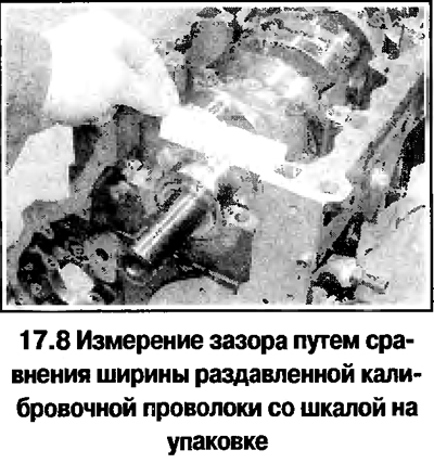
8. Install the covers with the lower liners without disturbing their orientation. Tighten the bolts in the sequence specified in the Technical Data (in 3 stages). During tightening, the position of the wire should not change, turning the crankshaft is not allowed. Evenly and gradually unscrew the cover bolts. Remove the covers (or frame), without disturbing the position of the flattened wires and without allowing the crankshaft to turn. Compare the width of the crushed wires with the scale on the package and determine the clearance in the main bearing (see photo). Compare with the standard value.
8. Install the covers with the lower liners without disturbing their orientation. Tighten the bolts…


9. If the gap differs from the standard, the reason may be the incorrect selection of liners (or their increased wear, if the liners tested were previously in use). If the flattened wire is wider at one end, this indicates that the journal is tapered. Before deciding whether the bearings need to be replaced, make sure that there was no dirt or oil between the covers or cylinder block and the bearing when measuring.


10. If the clearance exceeds the norm when measured with new liners, you should consult a car service center. It may be necessary to regrind the crankshaft journals and replace the liners with repair ones.

11. When finished, scrape off any remaining calibration wire from the crankshaft journals without damaging the surface.

Final installation of the crankshaft.

Engines 1.4, 1.6 and 1.8 l


12. Carefully remove the crankshaft from the cylinder block.

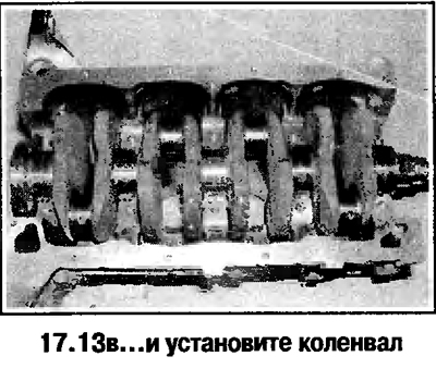
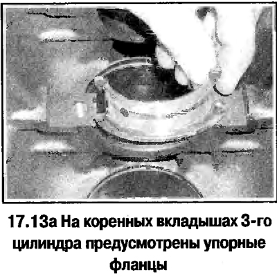
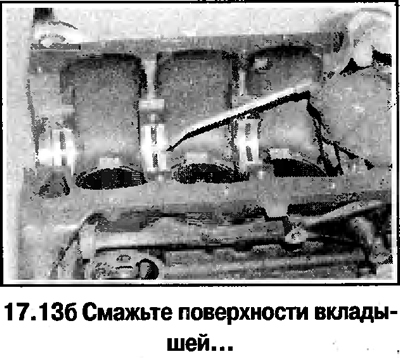
13. Install the main bearing shells in place. If new shells are installed, wash them thoroughly in kerosene and wipe dry. Generously lubricate the surfaces of the shells installed in the cylinder block with fresh engine oil (see photo).
13. Install the main bearing shells in place. If new shells are installed, wash them thoroughly in…


Material copied from this website OPELBOOK
13. Install the main bearing shells in place. If new shells are installed, wash them thoroughly in…


13. Install the main bearing shells in place. If new shells are installed, wash them thoroughly in…


14. Install the crankshaft into the cylinder block and check the axial clearance (see above).


15. Carefully clean the separating surfaces of the main bearing caps and the cylinder block from grease. Lubricate the surfaces of the lower bearing shells with engine oil. Make sure that the mounting protrusions on the bearing shells enter the recesses in the caps.

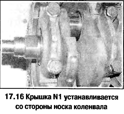
16. Install covers with numbers 1-4 in place (the 3rd cylinder liners are provided with thrust flanges), guided by the numbers applied (the numbers must face upwards and be read from the rear of the cylinder block).
16. Install covers with numbers 1-4 in place (the 3rd cylinder liners are provided with thrust…


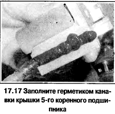
17. Fill the grooves of the 5th main bearing cap with sealant (see photo). The manufacturer recommends using OPEL 9048525 sealant. Install the cover in place.
17. Fill the grooves of the 5th main bearing cap with sealant (see photo). The manufacturer…


18. Lubricate the cover bolts and tighten by hand (see photo).


18. Lubricate the cover bolts and tighten by hand (see photo).


19. Tighten the cover bolts in a diagonal sequence in 3 stages (see Technical data).
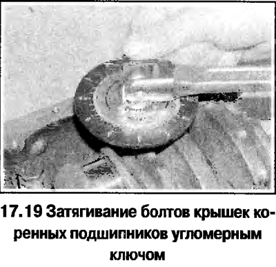
19. Tighten the cover bolts in a diagonal sequence in 3 stages (see Technical data).


20. After tightening the bolts, add sealant to the groove of the 5th bearing cap (see photo). The groove of the cover must be filled with sealant (the sealant should appear from under the joints). Remove excess sealant with a rag.
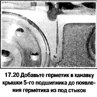
20. After tightening the bolts, add sealant to the groove of the 5th bearing cap (see photo). The…


21. Check the freedom of rotation of the crankshaft in the main bearings.


22. Install the connecting rods with pistons (see below).

23. Install the new rear oil seal

24. Install the flywheel, cylinder head, oil pump, oil deflector, oil pan and camshaft belt.

Engine 2.0 l


25. Install the crankshaft in the order described above.

26. Install the balance mechanism (or the frame of the lids), tighten the bolts to the specified torque

27. Install the new rear oil seal, flywheel, cylinder head, oil pump, oil deflector, pan and camshaft belt.


This article is available at russian, bulgarian, belarusian, ukrainian, serbian, croatian, romanian, polish, slovak, hungarian
Checking the article: Kornev Georgy

Share information:

Previous articles
Opel Astra G: Engine repair
Next articles

Piston rings — installation
Engine Overhaul — Assembly Procedure
Main and connecting rod bearings — inspection
Crankshaft — check
Connecting rod and piston group — check
Cylinder Block — Cleaning and Checking
Connecting rod and piston group — installation and checking of clearances in connecting rod bearings
Engine — Starting after major repairs


See similar ones from other Opel car manuals:
▶ Installing the crankshaft and checking the main bearing… Opel Corsa B (1993-2000)
▶ Checking the clearance in the crankshaft main bearings Opel Insignia A (2008-2017)
▶ Measuring clearances in crankshaft main bearings Opel Frontera B (1998-2004)
▶ Checking the diametrical clearance between the bearings and… Opel Kadett E (1984-1995)
▶ Crankshaft — installation and checking of main bearing… Opel Omega B2 (1999-2003)
Link to this page in different formats

Visitor comments


No comments yet


How much will 28 + 38 =


Astra J (2009-2015, petrol) 
  • General information
  • Vehicle device
  • User manual
  • Faults en route
  • Maintenance
  • Power unit
  • Engine repair
  • Cooling and lubrication system
  • Engine power system
  • Exhaust system
  • Transmission
  • Clutch
  • Car gearbox
  • Drive shafts
  • Chassis
  • Front suspension
  • Rear suspension
  • Steering
  • Brake system
  • Wheels and tires
  • Body
  • Exterior
  • Interior
  • Doors and windows
  • Body Care
  • Heating and air conditioning
  • Security systems
  • Electrical equipment
  • Equipment and devices
  • Lighting and signaling
  • Power devices
  • Electrical circuits
Astra H (2004-2009) 
  • General information
  • Introduction to the guide
  • Troubleshooting
  • User manual
  • Maintenance
  • Power unit
  • Engine repair
  • Cooling and heating
  • Power and exhaust system
  • Ignition system
  • Launch and charge system
  • Transmission
  • Mechanical gearbox
  • Automatic gearbox
  • Drive shafts
  • Chassis
  • Brake system
  • Car suspension
  • Steering
  • Body
  • Interior
  • Exterior
  • Electrical equipment
  • Equipment and devices
  • Electrical circuits
Astra G (1998-2004) 
  • General information
  • Introduction to manual
  • User manual
  • Maintenance
  • Power unit
  • SOHC gasoline engines
  • DOHC gasoline engines
  • Diesel engines 1.7 and 2.0
  • Engine repair
  • Cooling system
  • Supply system
  • Injection system (gasoline)
  • Injection system (diesel)
  • Exhaust system
  • Charge and launch system
  • Ignition system (gasoline)
  • Preheat system (diesel)
  • Transmission
  • Manual gearbox
  • Automatic gearbox
  • Clutch
  • Drive shafts
  • Chassis
  • Brake system
  • Wheel suspension
  • Steering
  • Body
  • Exterior
  • Interior
  • Doors and windows
  • Ventilation and heating
  • Electrical equipment
  • Equipment and devices
  • Electrical circuits
Astra G (1998-2004, petrol) 
  • General information
  • User manual
  • Car care
  • Maintenance
  • Power unit
  • Single shaft engines
  • Twin shaft engines
  • Engine repair
  • Cooling and heating
  • Fuel and exhaust systems
  • Starting and charging system
  • Ignition system
  • Transmission
  • Clutch
  • Mechanical gearbox
  • Automatic gearbox
  • Drive shafts
  • Chassis
  • Brake system
  • Car suspension
  • Steering
  • Body
  • Interior
  • Exterior
  • Electrical equipment
  • Equipment and devices
  • Wiring diagrams Opel Astra
  • Wiring diagrams Opel Zafira
Astra F (1991-1998, petrol) 
  • General information
  • Maintenance
  • Power unit
  • Engine in car
  • Engine removed
  • Cooling system
  • Heating and ventilation
  • Fuel supply (carburetor)
  • Fuel supply (injector)
  • Emission control
  • Ignition system
  • Transmission
  • Clutch
  • Mechanical gearbox
  • Automatic gearbox
  • Drive shafts
  • Chassis
  • Brake system
  • Car suspension
  • Steering
  • Body
  • Exterior
  • Interior
  • Electrical equipment
  • Equipment and devices
  • Electrical circuits
OpelBook.ru © 2017–2026 · Mobile version · · Sitemap: EN BG BY UA RS HR RO PL SK HU · Feedback · Site search
Astra F, petrol · Astra G, petrol · Astra G · Astra H · Astra J, petrol · Corsa B · Corsa C, petrol · Corsa C · Insignia A · Kadett D · Kadett E · Omega A · Omega B · Omega B2 · Vectra A, petrol · Vectra A · Vectra B, petrol · Vectra B · Vectra C · Zafira A, petrol · Frontera A, petrol · Frontera B · Ascona C · Vivaro A ·
We want your visit to be comfortable 🤝! We use cookies 🍪 to make that happen.