
Removing the crankshaft
The engine must be removed to remove the crankshaft.
In the following description, it is assumed that the necessary parts have already been removed in accordance with the description given.
Description of work is given separately for different types of engines.
Engine OHC 2.0 l
1. Drain the engine oil into a container by unscrewing the drain plug.
2. Remove the oil pan and oil pump as described in the appropriate section.
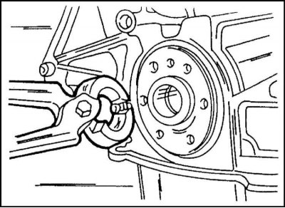
3. While holding the flywheel ring gear from turning with a screwdriver, unscrew the bolts of its fastening. In most cases, the bolts are loosened with a ring wrench without holding the flywheel. To do this, the spanner wrench is set at a right angle to the line passing through the axes of the flywheel and the bolt to be unscrewed, and it is struck by hand. To hold the clutch, a steel plate with two drilled holes is used. The plate is attached with flywheel bolts to the clutch. Support the engine and turn away bolts. Discard the bolts immediately, as they cannot be reused. Tighten the bolts to the required angle.
4. Remove the drive disk in the same way (Automatic transmission).
5. Turn away bolts and remove the pallet of a case.
6. Remove toothed belt and cylinder head (see separate description).
7. If it is necessary to remove only the crankshaft, the pistons with the connecting rod may remain in the cylinders. Otherwise, they must be removed as described earlier in the section Cylinder head and valves. If the pistons with connecting rods remain in the cylinders, mark the connecting rod caps and remove, store them with liners. The connecting rod bolts must be replaced.
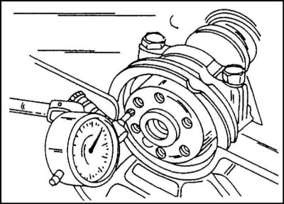
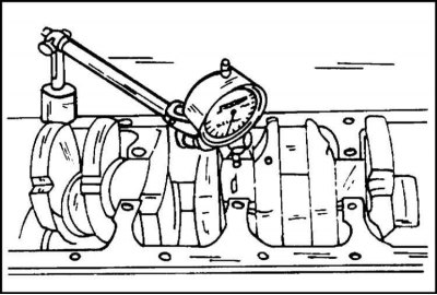
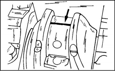
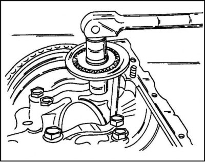
8. Install the indicator at the front side of the cylinder block so that its measuring tip rests on the extreme journal of the crankshaft, as shown in illustration. Press the crankshaft to one side with a screwdriver and set the indicator to zero. Press the crankshaft to the other side. The indicator reading represents the end play of the crankshaft. Record the resulting value. If the play is outside the specified limits, this must be taken into account during assembly.
In the absence of an indicator, play can be measured with a feeler gauge on the center bearing between the bearing flange and the plane of the crankshaft.
9. Mark the main bearing caps and unscrew the bolts of their fastening evenly from the outside towards the inside. Remove covers. Check that the cap numbers are clearly visible.
10. Remove the liners from the crankshaft journals and store them complete with the appropriate cover.
11. Remove thrust half rings from one of the bearings to adjust the axial play.
12. Carefully remove the crankshaft from the cylinder block. Be careful not to damage the speed sensor gear, if equipped.
13. Take out from the lower part of the block of cylinders the remained loose leaves and connect in one set with other halves and covers. Label the inserts.
Engine OHC 2.4 l
1. Install and fix the engine on the stand.
2. Drain the engine oil into a container by unscrewing the drain plug.
3. Remove the cylinder head as described for the engine in question.
4. Loosen the viscous fan mounting bolt as shown in illustration. On the reverse side, the fan is held with a hexagon wrench. The details of this operation are described in the corresponding section.
Attention! The fan mounting bolt has a left-hand thread.
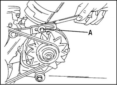
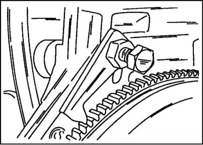
5. Loosen the bolt (A) fastening the generator tensioner in the illustration, press the generator inward and remove the V-belt.
6. Turn away a bolt of fastening of a cable of weight from a head of cylinders, wring out the generator down and remove together with an arm, having disconnected the last.
7. Remove the terminal bolt at the base of the ignition distributor and remove the distributor.
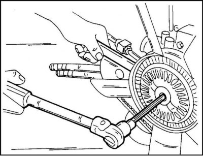
8. Unscrew the bolt securing the crankshaft pulley with a spanner wrench, holding the flywheel with a screwdriver from turning. There is also a special lock to hold the flywheel.
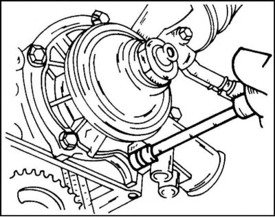
9. Turn away bolts of fastening and remove the pump of a cooling liquid (illustrations).
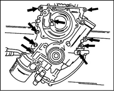
10. Remove the camshaft drive chain tensioner, timing drive housing and oil pan in the order shown. If the engine is in the position shown in the illustration, unscrew the bolts shown by the arrows.
11. Remove the helical gear from the distributor shaft.
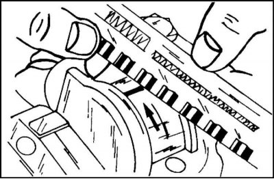
12. Apply paint to the drive chain with an arrow indicating the direction of its rotation and remove the sprocket along with the chain.
13. Remove the crankshaft sprocket with a puller. Be sure to place a gasket between the thrust screw of the puller and the end of the crankshaft.
14. Mark the mutual position of the clutch basket and flywheel, unscrew the bolts and remove the basket. Description of disassembly of the clutch is given in the appropriate section. Lock bolt screwed into flywheel (illustrations). Its position must be noted before disassembling the assembly.
15. Label all connecting rod bearing caps starting with a number "1" from the coolant pump side.
Turn away bolts and remove a reception pipe of the oil pump.
16. If only the crankshaft needs to be removed, the pistons with the connecting rods may remain in the cylinders. Otherwise, both pistons and connecting rods are removed as described in section Cylinder head and valves. If the pistons and connecting rods remain in the cylinder block, mark the connecting rod caps in order and remove them together with the liners.
17. Measure the end clearance of the crankshaft.
Install the indicator at the front side of the cylinder block so that its measuring tip rests on the extreme journal of the crankshaft, as shown in illustration. 8. Press the crankshaft to one side with a screwdriver and set the indicator to zero. Press the crankshaft to the other side. The indicator reading represents the end play of the crankshaft. Record the resulting value. If the play is outside the specified limits, this must be taken into account during assembly.
In the absence of an indicator, play can be measured with a feeler gauge on the center bearing between the bearing flange and the plane of the crankshaft.
18. Mark the main bearing caps and unscrew the bolts of their fastening evenly from the outside towards the inside. Remove covers. Check that the cap numbers are clearly visible.
19. Remove the liners from the crankshaft journals and store them complete with the appropriate cover.
Remove thrust half rings from one of the bearings to adjust the axial play.
20. Carefully remove the crankshaft from the cylinder block. Be careful not to damage the speed sensor gear, if equipped.
21. Take out from the lower part of the block of cylinders the remained loose leaves and connect in one set with other halves and covers. Label the inserts.
DOHC engine
1. Fix the engine on the stand, unscrew the bolts and disconnect the engine suspension beam from the cylinder block.
2. If the engine oil has not yet been drained, remove the drain plug and drain the oil into a container.
3. Remove the oil pan and oil pump as described in the appropriate section. In this case, the year of manufacture of the car must be taken into account, since after 1997 the design of the oil pump was changed.
4. For an engine manufactured in 1997, remove the bearing bridge and oil baffle plate. This work is described separately.
5. While holding the flywheel ring gear from turning with a screwdriver, unscrew the bolts of its fastening. In most cases, the bots are turned away with a ring wrench without holding the flywheel. To do this, the spanner wrench is set at right angles to the line passing through the axes of the flywheel and the bolt to be unscrewed, and a blow is applied to it by hand. A steel plate with two drilled holes is used to hold the clutch. The plate is attached with flywheel bolts to the clutch. Support the engine and turn away bolts. Discard the bolts immediately, as they cannot be used. Bolts tighten with angular control.
6. Remove toothed belt and cylinder head (see separate description).
7. If it is necessary to remove only the crankshaft, the pistons with the connecting rod may remain in the cylinders. Otherwise, they must be removed as described in section Cylinder head and valves. If the pistons with connecting rods remain in the cylinders, mark the connecting rod caps and remove, store them with liners. The connecting rod bolts must be replaced.
8. Install the indicator at the front side of the cylinder block so that its measuring tip rests on the extreme neck of the crankshaft, as shown in illustration. 8. Press the crankshaft to one side with a screwdriver and set the indicator to zero. Press the crankshaft to the other side. The indicator reading represents the end play of the crankshaft. Record the resulting value. If the play is outside the specified limits, this must be taken into account during assembly.
In the absence of an indicator, play can be measured with a feeler gauge on the center bearing between the bearing flange and the plane of the crankshaft.
9. Mark the main bearing caps and unscrew the bolts of their fastening evenly from the outside towards the inside. Remove covers. Check that the cap numbers are clearly visible.
10. Remove the liners from the crankshaft journals and store them complete with the appropriate cover.
Remove thrust half rings from one of the bearings to adjust the axial play.
11. Carefully remove the crankshaft from the cylinder block. Be careful not to damage the speed sensor gear, if equipped.
12. Take out from the lower part of the block of cylinders the remained loose leaves and connect in one set with other halves and covers. Label the inserts.
Checking the parts of the crankshaft
1. Carefully check the crankshaft for damage and measure the diameters of the connecting rod and main journals. The connecting rod and main journals can be reground several times, after which the bearings of a reduced repair size can be used. Due to the presence of various markings, the choice of liners is quite difficult. Therefore, the operation in question is best performed in a car repair shop.
2. Install the crankshaft at the centers of the lathe (or into prisms with trunnions) and check the runout of the middle main journal with an indicator. The runout should not exceed 0.03 mm. If the specified value is exceeded, the crankshaft is replaced. In the absence of an indicator, the crankshaft can be laid with well-cleaned liners in the cylinder block and the runout of the middle journal can be measured with an indicator (see illus.).
3a. Measure the main and connecting rod bearing clearances:
- Thoroughly clean the liners and install them in the bed of the cylinder block or connecting rods.
- Lay pieces of plastic wire "Plastigage" on all main journals, as shown in fig. 3a, and close the necks with bearing caps with liners.
Tighten the cap screws to the specified torque. In this case, the crankshaft must not be rotated.
3b. To control the clearances in the connecting rod bearings, install the connecting rods on the crankshaft journals and lay pieces of plastic wire on top "Plastigage". Close the necks with connecting rod caps and tighten the fastening nuts to the specified torque. In this case, turning the crankshaft is unacceptable. Therefore, the measurement is performed only for the two connecting rod journals located at BDC.
- Loosen the main bearing cap bolts and connecting rod bolts.
- With the included gauge "Plastigage" measure the maximum thickness of flattened wire (illustrations 3b). If the resulting value "Plastigage" is outside the specified limits, it is necessary to install new bearing shells 3. In this case, it is necessary to determine whether the shaft journals have not been ground before.
- Turn the crankshaft and measure the clearance in the bearings of the other two connecting rod journals.
Installing the crankshaft
OHC 2.0 engine
If the gear wheel of the TDC sensor of the crankshaft was removed, it is necessary to install it in place and fix it with bolts with a torque of 13 Nm (from the middle of 1995 release).
1. With a manual transmission installed, if necessary, replace the pilot bearing at the end of the crankshaft.
2. Wipe the beds of the bearings in the cylinder block and place the liners in them in accordance with the marking so that the protrusions of the liners enter the grooves of the beds. If the cylinder block came after grinding, in most cases new liners are installed.
They should also be labelled. Lubricate the liners generously with oil before laying.
3. Reinstall both thrust washers in the cylinder block. The oil grooves must face the block.
4. Carefully place the crankshaft into the main bearings. If the pistons with connecting rods are in the cylinder block, carefully guide the connecting rods onto the crankshaft crankpins.
5. Install the shells in the main bearing caps (protrusions into grooves) and grease them generously.

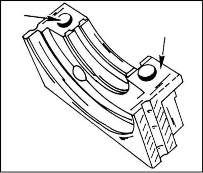
6. Install the bearing caps in the cylinder block seats and tap them with a rubber mallet. Covers must be installed in accordance with the markings. In addition, the inside surface of the front and rear covers on the outside, right and left should be lubricated with sealant, as shown in illustration. Only the surfaces shown by the arrows are lubricated. There are grooves on the outer sides of both covers. They are filled with sealant.
Instruction. After installing the covers, press the sealant on top again so that it protrudes from the grooves.
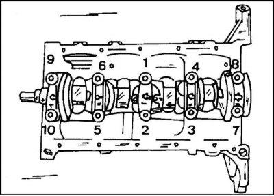
7. Tighten the new cover bolts from the center to the edges in the sequence shown in illustration. in several steps with a torque of 50 Nm. After tightening to the specified torque, replace the torque wrench with a lever and tighten the bolts to an angle of 40°–50°. The illustration applies to all types of engines.
8. After installing the covers, fill the gaps to the right and left of the first cover with sealant so that the sealant comes out at the points of contact with the cylinder block (see note above).
9. Turn the crankshaft several times, identifying possible jams.
10. Check the end play again as described when removing the crankshaft (see illus. 8).
11. Install the connecting rod and piston group as described above.
12. Install both seals.
13. Install the keyed gear.
14. Put on a toothed belt, as described in Section Camshaft drive.

15. Install flywheel (see relevant subsection) and secure it with screws. To hold the crankshaft from turning, insert a block of wood between the crankshaft journal and the cylinder block wall, or hold the crankshaft from turning in some other way (illustration, for all engines).
16. Fit the clutch to the flywheel as marked. Center the clutch disc accordingly. Tighten the mounting bolts evenly and crosswise.
17. Install the oil pump (see Section Work with the lubrication system on the engine 2.4 l).
18. Install the oil pan, screw in the drain plug and tighten it to 55 Nm. Now, if necessary, engine oil can be poured into the engine.
19. Establish other details in sequence, return to removal.
OHC 2.0 L engine from mid-1995 release
The installation of the crankshaft in this case is carried out similarly to the description given, taking into account the following:
1. Fill the grooves on the outside of the rear main bearing cap with sealant. After installing the cover, insert the sealant from above again so that it protrudes from the groove. The places shown in the illustration on the engine are no longer lubricated with sealant.
2. Bolts of fastening of covers of radical bearings tighten the moment of 50 Nm and from this position tighten on an angle 45°and then on 15°. To do this, it is advisable to use a graduated scale, as shown in the illustration.
3. Install the bearing bridge and the oil flinger as described in section Lubrication system.
4. Install the oil pump and oil pan as described in the appropriate subsection.
5. Attach the lugs to the engine, tighten the bolts to 60 Nm.
6. Screw in and tighten the drain plug to 45 Nm.
Engine OHC 2.4 l
1. Wipe the bearing beds in the cylinder block and place the liners in them in accordance with the marking so that the protrusions of the liners enter the grooves of the beds. If the cylinder block came after grinding, in most cases new liners are installed. They should also be labelled. Lubricate the liners generously with oil before laying.
2. Carefully place the crankshaft into the main bearings. If the pistons with connecting rods are in the cylinder block, carefully guide the connecting rods onto the crankshaft crankpins.
3. Install the shells in the main bearing caps (protrusions into grooves) and grease them generously.

4. Install the bearing caps in the cylinder block seats and tap them with a rubber mallet. Covers must be installed in accordance with the markings. In addition, the inside surface of the front and rear covers on the outside, right and left should be lubricated with sealant, as shown in illustration. Only the surfaces shown by the arrows are lubricated. Grooves on the outer sides of both covers (width about 6mm). They are filled with sealant.
Instruction. After installing the covers, press the sealant on top again so that it protrudes from the grooves.

5. Tighten by hand the bolts of the main bearing caps from the middle to the edges in the sequence shown in the illustration. Before final tightening, install the rear bearing seal as described in a separate subsection. After that, tighten the bolts in several steps in the prescribed sequence to a torque of 110 Nm.
6. After installing the covers, fill the gaps to the right and left of the first cover with sealant so that the sealant comes out at the points of contact with the cylinder block (see note above).
7. Turn the crankshaft several times, identifying possible jams.
8. Check the end play again as described when removing the crankshaft (see also illus. paragraph 5 here). For this motor, the axial clearance must not exceed 0.152 mm.
9. Install the connecting rod and piston group as described above.

10. Install the flywheel, paying attention to the position of the fixing bolt and finger-tighten the bolts. While holding the flywheel ring gear from turning, tighten the fastening bolts evenly to 60 Nm.
11. Install the clutch as described in the appropriate section.
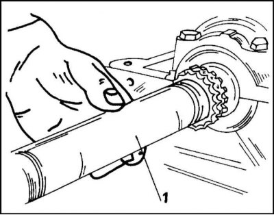
12. Press the sprocket with a pipe (1), as shown in illustration. on the crankshaft until it stops.
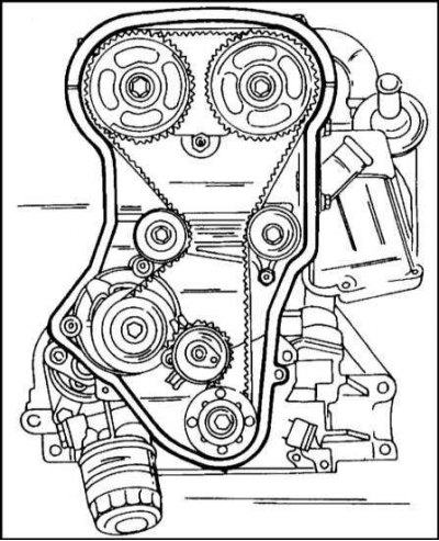
13. Install the following parts in order: drive chain, chain cover, coolant pump, pulley, viscous fan. The description of these works is given separately.
14. Install the following parts in the order shown below: oil pan, cylinder heads, ignition distributor, alternator, compressor (with air conditioning). Installation details are described in the following sections.
15. Install the rest of the parts in the reverse order of their removal.
DOHC engine
1. If the gear wheel of the TDC sensor of the crankshaft was removed, it is necessary to install it in place and fix it with bolts with a torque of 13 Nm (from the middle of 1995 release).
2. For manual transmission, replace the pilot bearing at the end of the crankshaft if necessary.
3. Wipe the beds of the bearings in the cylinder block and place the liners in them in accordance with the marking so that the protrusions of the liners enter the grooves of the beds. If the cylinder block came after grinding, in most cases new liners are installed. They should also be labelled. Lubricate the liners generously with oil before laying.
4. Reinstall both thrust washers in the cylinder block. The oil grooves must face the block.
5. Carefully place the crankshaft into the main bearings. If the pistons with connecting rods are in the cylinder block, carefully guide the connecting rods onto the crankshaft crankpins.
6. Install the shells in the main bearing caps (protrusions into grooves) and grease them generously.

7. Install the bearing caps in the cylinder block seats and tap them with a rubber mallet. Covers must be installed in accordance with the markings. In addition, the inside surface of the front and rear covers on the outside, right and left should be lubricated with sealant, as shown in illustration. Only the surfaces shown by the arrows are lubricated. There are grooves on the outer sides of both covers. They are filled with sealant.
Instruction. After installing the covers, press the sealant on top again so that it protrudes from the grooves.

8. Tighten the new cover bolts from the center to the edges in the sequence shown in the illustration in several steps to a torque of 50 Nm. After tightening to the specified torque, replace the torque wrench with a lever and tighten the bolts to a 45°angle. Finally, retighten all bolts again by 15°.
9. After installing the covers, fill the gaps to the right and left of the first cover with sealant so that the sealant comes out at the points of contact with the cylinder block (see note above).
10. Turn the crankshaft several times to identify possible jams.
11. Check the end play again as described when removing the crankshaft (see also illus. 8).

12. Install the connecting rod and piston group as described above. Tighten the caps to a torque of 35 Nm and then tighten by 45°and again by 15°. To do this, it is recommended to use a graduated washer, as shown in the illustration.
13. Install both seals (see below).
14. Install the keyed gear.
15. Put on a toothed belt, as described in Section Camshaft drive.
16. Install flywheel (see relevant subsection) and secure it with screws. To hold the crankshaft from turning, insert a block of wood between the crankshaft journal and the cylinder block wall, or hold the crankshaft from turning in some other way (illustration, for all engines).
17. Fit the clutch to the flywheel as marked. Center the clutch disc accordingly. Tighten the mounting bolts evenly and crosswise.
18. For engines since 1997, install the bearing axle and oil baffle plate. These works are described in Section Lubrication system.
19. Install the oil pump (see section Work with the lubrication system on the engine 2.4 l).
20. Install the oil pan, screw in the drain plug and tighten it to 45 Nm. Now, if necessary, engine oil can be poured into the engine.
21. Establish other details in sequence, return to removal.
Crankshaft seals
OHC and DOHC 2.0L engines
After each removal of the crankshaft, the front and rear oil seals must be replaced with new ones. No special tool is required for this. Oil seals can be replaced without removing the engine if an oil leak is found in their area.
A leak in the rear oil seal can, for example, be the cause of a slipping clutch. The front oil seal is located in the oil pump housing.
Removal of glands
General instructions apply to all engines. Replacing the front oil seal is associated with the removal of the oil pump housing, since that is where the oil seal is located. Relevant instructions are given in Section Lubrication system.
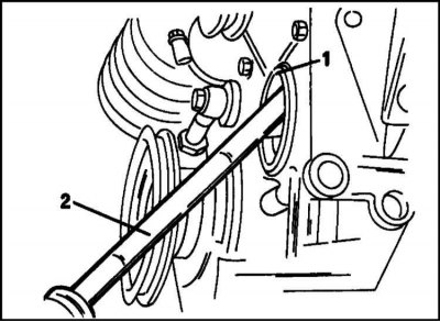
1. To remove the front oil seal with a sharp mandrel, punch a hole in the metal ring of the oil seal, screw in a self-tapping screw and pull out the oil seal with pliers, as shown in the illustration. All seals can be removed in this way.
2. To remove the rear oil seal, you must remove the gearbox, clutch and flywheel. The gland is removed in the manner described above using a self-tapping screw (see illus. paragraph 1 here). Be careful not to damage the cylinder block.
Installation of oil seals
1. Lubricate the seal lip and outer surface of the seal with grease and carefully press the seal flush with the outer surface. You can use a piece of pipe installed on the outer perimeter of the stuffing box and clamped on top with a washer. In this case, the oil seal can be pressed in with a bolt securing the crankshaft pulley.
2. Further, it is necessary to proceed in accordance with the description of the installation of the oil pump.
3. The rear oil seal is pressed in carefully with a hammer. Be careful not to damage the sealing surface. Lubricate the working and outer surfaces with oil or grease. The gland is pressed in using a piece of pipe of the appropriate diameter flush with the outer plane. Other parts are installed in the reverse order of removal (flywheel, clutch, etc.)
Engine OHC 2.4 l
With this engine, the front oil seal is located in the cover of the distribution drive housing, the rear oil seal is in the back cover.
Replacing the front oil seal
1. Disconnect the ground cable from the battery.
2. Remove the fan cover and hang under the impeller.
3. Remove the viscous fan. Its mounting bolt has a left-hand thread (see chapter Cooling and heating systems).
4. Remove the alternator oil pump drive V-belt as described in the relevant subsections. To loosen the belt tension, loosen the tensioner.
5. Remove the crankshaft wheel while holding the crankshaft from turning (turn on the transmission).
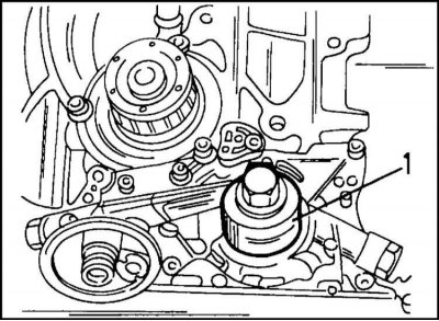
6. Remove the front seal (1) with a screwdriver (2) from the camshaft drive cover, as shown in illustration.
7. Lubricate the working surface of the oil seal with grease and press it all the way into the cover. There is a special tool for this. You can also use a piece of pipe (1) appropriate diameter, washer and bolt as shown in fig.
8. Install the crankshaft pulley and, holding the pulley from turning, tighten its fastening bolt to 120 Nm.
9. Install and tension the alternator and oil pump drive V-belt.
10. Install a viscous fan (see separate description).
11. Install the fan shroud and connect the battery.
Replacing the rear oil seal
1. Remove the gearbox (see related section).

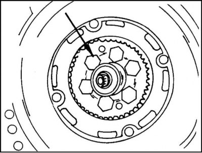
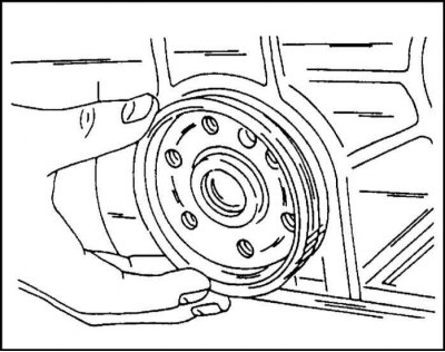
2. Mark the position of the guide bolt in the flywheel (marked with a letter "R"). Holding the flywheel from turning (see illus.), remove the flywheel bolts. Remove flywheel.
Attention! He can easily fall

3. Punch a hole in the stuffing box with a sharp mandrel, screw a self-tapping screw into it and pull out the stuffing box, as shown in the illustration.
4. Lubricate the outer and running surfaces of the oil seal with grease and insert it into the hole as shown in illustration. Press in the seal with a mandrel until it stops.
5. Install and secure the flywheel, paying attention to the position of the guide bolt. Crimp the bolts evenly around the circumference with a torque of 60 Nm.
6. Install the clutch and gearbox.
Flywheel
The flywheel of the engines in question is bolted directly to the rear flange of the crankshaft.
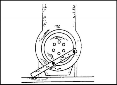
1. To remove the flywheel, block it with a screwdriver inserted into the ring gear or with a pawl. It is recommended to block the flywheel in the manner described for removing the crankshaft (see illus.). The engine must be securely fastened. Mark position of flywheel before removal.
Engine 2.4 l
This engine has a guide bolt in the flywheel, marked with the letter "R". Before unscrewing the fastening bolts, mark the position of the guide bolt. Its marking is shown in Fig. 2.
OHC 2.0 L engine from mid-1995 release
The air-conditioned vehicle has a dual mass flywheel. Removing it is similar to removing a conventional flywheel.
DOHC engine
The flywheel mount is similar to the flywheel mount for the 2.0L OHC engine. When installing, pay attention to the installation time (see below).
2.0 L OHC engine up to mid 1995 release
The flywheel bolts should not be reused. Tighten the new bolts to the specified torque and tighten to the required angle.
1. Lubricate the threads of the bolts with a locking agent "Loctite".
2. First tighten the bolts to a torque of 65 Nm, and then tighten by an angle of 30°–45°. Bolts must be tightened within 5 minutes (drying time "Loctite").
Engine 2.0 l since the middle of 1995 of release
The flywheel mounting bolts are not used a second time. They are first tightened to a predetermined torque, and then pulled twice to a predetermined angle. The tightening must be done within 5 minutes, including tightening.
1. Tighten the bolts evenly around the circumference to a torque of 65 Nm.
2. Pull the boots up to a 30°angle.
3. Tighten the bolts again at an angle of 15°.
Engine OHC 2.4 l
Screw the fixing bolt shown in the illustration according to the marking. 10 and tighten the fastening bolts evenly around the circumference to 60 Nm.
DOHC engine
Tighten the bolts to the specified torque, and then tighten them twice to the specified angle. The tightening must be done within 5 minutes, including tightening.
1. Tighten the bolts evenly around the circumference to a torque of 65 Nm.
2. Pull the boots up to a 30°angle.
3. Tighten the bolts again at an angle of 15°.
Instruction. Tightening is best performed using a graduated scale, as shown in fig. 12.
OHC 2.0 engine and DOHC engine since mid 1995
These engines have an engine speed sensor gear under the flywheel. The wheel is removed only if the crankshaft is replaced.
1. Tighten the wheel bolts to 13 Nm.
Flywheel ring gear
The ring gear for driving the engine with a starter is pressed onto the flywheel and can be replaced.
1. It may be necessary to heat up to 70°C to remove the crown. In this case, it is advisable to carry out the work in a car workshop.
If the friction surface of the flywheel is burred, the flywheel must be replaced.
Automatic transmission drive plate
The same work is done with the drive disk as with the flywheel. The tightening torques are the same as those indicated in the last subsection. Always replace disc mounting bolts with new ones.
Replacing the guide bearing
A guide bearing is installed at the end of the crankshaft. If the bearing is damaged, it is replaced with a new one (with manual gearbox).
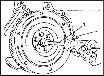
1. The bearing is removed with a puller using a hammer with a sliding head, see illustration.
If there is damage to the pilot bearing, the gearbox input shaft journal must also be checked.
The new bearing is lubricated with high temperature grease and pressed with a mandrel into the end of the crankshaft.
Visitor comments