


Contents: Removal ⬇ Installation ⬇
All instructions regarding removal and installation of the OHC engine also apply in this case. The engine is removed from the compartment without the gearbox. The gearbox and transfer case must be removed separately to allow the engine to be removed without being blocked by the gearbox.
Removal
1. Disconnect the ground cable and positive cable from the battery.
2. Remove the hood. First, set the hood to a vertical position and disconnect the hose supplying fluid to the windshield washer nozzles. Use a pencil to trace the hinges on the surface of the sheet metal hood so that you can later install the hood in its original position. Loosen the hinge mounting screws. In this case, the assistant must hold the hood. Remove the hood and place it in a well-protected place. Place a thick cloth under the edges of the hood.
3. Drain the cooling system (Section Filling the cooling system coolant Chapters Routine care and maintenance) and close the system hoses with plugs. These include three radiator hoses, a hose between the coolant expansion tank and the coolant supply line at the intake manifold, a coolant drain hose from the intake manifold, and water supply and drain hoses to the heater.
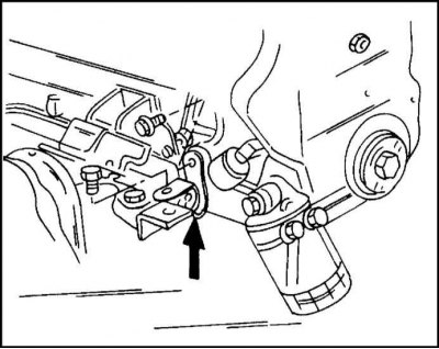
4. Disconnect the ground cable from the engine battery at the point shown in the illustration. The arrow indicates the location of the engine ground cable connection.
5. Disconnect the wiring harness from the engine. It is mounted in several places: in the multi-position plug and socket on the wall of the engine compartment, in the multi-position plug and socket at the branch of the engine wiring harness in front on the right, at the fuse box, at the temperature sensor, at the air mass meter and at the oxygen sensor. It is recommended to mark the connections to facilitate their further assembly.
6. Remove the radiator and cooling fan as described in the appropriate section.
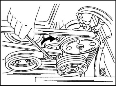
7. Place an arrow on an easily accessible place on the V-belt indicating the direction of its rotation. Turn the belt tension roller as shown in the illustration in the direction of the arrow so that the belt becomes loose and remove it.
8. Remove the power steering pump. To do this, unscrew the bolt from the console and the pump bolts. Remove the pump and tie it with wire to some structural element. Do not open the hydraulic system, do not hang the pump on the hoses.
9. If you have air conditioning, remove the compressor. To do this, disconnect the compressor bracket from the cylinder block and the unit console. Fastening is carried out with three bolts at the front and four at the back.
10. Release the throttle cable from the holder and remove.
11. Disconnect the vacuum hose from the suction line.
12. Disconnect both fuel lines at the end connections.
Attention! When opening a pipeline under pressure, fuel is released. Do not place the test lamp nearby under any circumstances. When opening a connection, it is recommended to put a wrench on it and cover it with a rag on top. After this, slowly unscrew the hollow bolt.
13. Unscrew the oil hose connection from the oil filter head. Please note the presence of a sealing ring.
14. Disconnect the two coolant hoses from the throttle body. Also disconnect the vacuum hose going to the evaporator control valve.
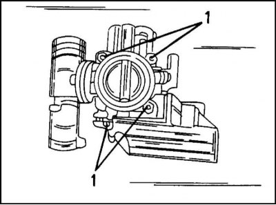
15. Remove the four mounting bolts (1) shown in the illustration and remove the throttle body and intake manifold.
16. Now disconnect the cable at the end of the ball head. The cable is secured to the support with a spring clamp, which must be removed. After releasing the clamp, the cable can be disconnected.
17. Loosen the union nut and disconnect the brake booster vacuum hose from the intake manifold.
18. If present, remove the bottom protective sheet from below (to do this, place the car on stands).
19. Unclip from the bottom of the car (put the car on stands) oxygen sensor plug connection. Loosen the exhaust system bracket mounting bolts and remove the exhaust pipe with the catalytic converter from the muffler.
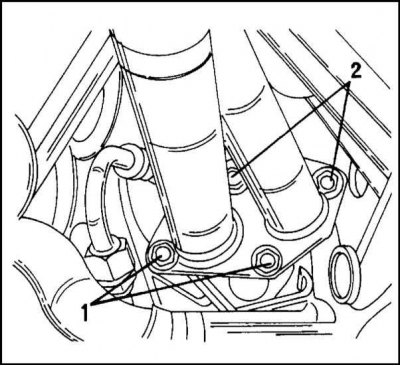
20. Remove bolts (1) and (2) shown in the illustration. and disconnect the exhaust pipe, with the catalytic converter attached to it, from the exhaust manifold. Lower the entire assembly down and remove it.
21. Disconnect the coolant hose from the line.
22. Remove the gearbox and transfer case as described in the appropriate section. After this, only one engine remains on the suspension.
23. Attach lifting cables or chains to the engine lugs and lift the engine. Remove the suspension and lift the engine up, separating it from the suspensions. Be careful not to damage any cable connections or pipes, and be careful not to hit the engine against any components in the engine compartment. It is recommended to perform the operation with an assistant.
Installation
The engine is installed in the reverse order of removal. Most of the instructions for installing an OHC engine also apply to a DOHC engine. The fuel lines are tightened to a torque of 15 Nm. It is necessary to hold the nipple with a wrench to prevent damage from the tightening torque.
Visitor comments