


F4R petrol engine of car Opel Vivaro A

Tightening the cylinder head
Tightening torque, Nm Cylinder head mounting bolts - 20 Nm + 165° ±6°. You can reuse bolts if the bolt length does not exceed 118.5 mm (otherwise replace all...
Tightening torque, Nm Cylinder head mounting bolts - 20 Nm + 165° ±6°. You can reuse bolts if the bolt length does not exceed 118.5 mm (otherwise replace all...

Adjusting the engine accessory drive belt
1. Place the vehicle on a two-post lift. 2. Disconnect the battery. 3. Remove the engine cover, right front wheel, engine sump. 4. Rotate the belt tensioner in...
1. Place the vehicle on a two-post lift. 2. Disconnect the battery. 3. Remove the engine cover, right front wheel, engine sump. 4. Rotate the belt tensioner in...

Volumes of working fluids
Engine Engine Average oil capacity, l F4R Drain Draining and replacing the oil filter 5.25 5.41 Transmission Manual transmission Volume, l RK 6 2.7 Note: Never...
Engine Engine Average oil capacity, l F4R Drain Draining and replacing the oil filter 5.25 5.41 Transmission Manual transmission Volume, l RK 6 2.7 Note: Never...

Removal and installation the engine
Removal 1. Place the vehicle on a two-post lift. Caution: During this operation, secure the vehicle with a belt to avoid instability. 2. Remove the carpet...
Removal 1. Place the vehicle on a two-post lift. Caution: During this operation, secure the vehicle with a belt to avoid instability. 2. Remove the carpet...

Removal and installation the timing belt
Removal 1. Place the vehicle on a two-post lift. 2. Remove the carpet under the left seat and the battery cover 1 (figure 2.3). 3. Disconnect the battery. 4....
Removal 1. Place the vehicle on a two-post lift. 2. Remove the carpet under the left seat and the battery cover 1 (figure 2.3). 3. Disconnect the battery. 4....

Engine technical data
Permissible deformation Cylinder head - 0.05 mm. Cylinder block - 0.03 mm. Pistons The piston dimensions are shown in the figure 2.42. Figure 2.42. Piston...
Permissible deformation Cylinder head - 0.05 mm. Cylinder block - 0.03 mm. Pistons The piston dimensions are shown in the figure 2.42. Figure 2.42. Piston...

Technical characteristics of fuel injection system components
The content of harmful substances in exhaust gases is given in Table 2.1. Table 2.1. Content of harmful substances in exhaust gases Idle control (warm engine)*...
The content of harmful substances in exhaust gases is given in Table 2.1. Table 2.1. Content of harmful substances in exhaust gases Idle control (warm engine)*...
Removal and installation the throttle body
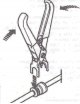
Removal 1. Disconnect the fuel line using pliers Mot. 1265 (figure 2.49). Figure 2.49. Disconnect the fuel line using pliers Mot. 1265. 2. Remove the air...
Removal 1. Disconnect the fuel line using pliers Mot. 1265 (figure 2.49). Figure 2.49. Disconnect the fuel line using pliers Mot. 1265. 2. Remove the air...

Removal and installation the intake manifold
Removal the upper part of the intake manifold 1. Disconnect the battery. 2. Remove the air filter housing. 3. Disconnect the wiring connector from the throttle...
Removal the upper part of the intake manifold 1. Disconnect the battery. 2. Remove the air filter housing. 3. Disconnect the wiring connector from the throttle...

Removal and installation the exhaust manifold
Removal 1. Place the vehicle on a two-post lift. 2. Disconnect the battery. 3. Remove the air filter. 4. Remove the engine sump. 5. Place a support under the...
Removal 1. Place the vehicle on a two-post lift. 2. Disconnect the battery. 3. Remove the air filter. 4. Remove the engine sump. 5. Place a support under the...

Removal and installation of fuel rail and injectors
The injectors are attached to the fuel rail using clamps. Fuel circulates continuously around the perimeter of the injector body. The constant movement of...
The injectors are attached to the fuel rail using clamps. Fuel circulates continuously around the perimeter of the injector body. The constant movement of...

Removal and installation of pistons and connecting rods
Removal 1. To prevent the crankshaft from turning, screw in the two bolts 1 securing the flywheel to the crankshaft, then insert the lever 2 between the two...
Removal 1. To prevent the crankshaft from turning, screw in the two bolts 1 securing the flywheel to the crankshaft, then insert the lever 2 between the two...

Removal and installation oxygen sensors
14.1. Oxygen sensor before catalytic converter Removal 1. Raise the vehicle. 2. Disconnect the oxygen sensor wiring connector 2 from the wiring harness 1...
14.1. Oxygen sensor before catalytic converter Removal 1. Raise the vehicle. 2. Disconnect the oxygen sensor wiring connector 2 from the wiring harness 1...

Removal and installation the accelerator pedal position sensor
Caution: Make sure the ignition is off. 15.1. Left-hand drive vehicles Removal 1. Disconnect the wiring connector 1 (figure 2.74). Remove sensor 2 from the...
Caution: Make sure the ignition is off. 15.1. Left-hand drive vehicles Removal 1. Disconnect the wiring connector 1 (figure 2.74). Remove sensor 2 from the...

Removal and installation the crankshaft speed sensor
Removal 1. Remove resonator 3 with air duct from the air filter (figure 2.76). To do this, remove clamp 1 from support bracket 2. Figure 2.76. Remove resonator...
Removal 1. Remove resonator 3 with air duct from the air filter (figure 2.76). To do this, remove clamp 1 from support bracket 2. Figure 2.76. Remove resonator...

Removal and installation the coolant temperature sensor
Removal 1. Remove resonator 3 with air duct from the air filter (figure 2.76). To do this, remove clamp 1 from support bracket 2. 2. Disconnect wiring...
Removal 1. Remove resonator 3 with air duct from the air filter (figure 2.76). To do this, remove clamp 1 from support bracket 2. 2. Disconnect wiring...

Removal and installation the intake air temperature sensor
Removal 1. Disconnect wiring connector 1 from intake air temperature sensor 2 (figure 2.82). 2. Remove the intake air temperature sensor 1 from the intake...
Removal 1. Disconnect wiring connector 1 from intake air temperature sensor 2 (figure 2.82). 2. Remove the intake air temperature sensor 1 from the intake...

Removal and installation the knock sensor
Removal 1. Raise the vehicle. 2. Remove the engine protection by unscrewing six bolts 1 (figure 2.78). 3. Disconnect the wiring connector 1 from the knock...
Removal 1. Raise the vehicle. 2. Remove the engine protection by unscrewing six bolts 1 (figure 2.78). 3. Disconnect the wiring connector 1 from the knock...

Removal and installation the generator
Removal 1. Place the car on a lift 2. Remove the carpet under the left seat and the battery cover 1 (figure 2.86). 3. Disconnect the battery. 4. Remove the...
Removal 1. Place the car on a lift 2. Remove the carpet under the left seat and the battery cover 1 (figure 2.86). 3. Disconnect the battery. 4. Remove the...

Removal and installation the starter
Engine starting system The F4R 720 engine is equipped with a Bosch 0001106023 starter. Removal 1. Removing the starter requires removing the catalytic...
Engine starting system The F4R 720 engine is equipped with a Bosch 0001106023 starter. Removal 1. Removing the starter requires removing the catalytic...

Removal and installation the ignition coil
Removal 1. Disconnect the battery. 2. Disconnect the ignition coils. Attention! Damaged connectors must be completely replaced. 3. Unscrew the bolts 2 securing...
Removal 1. Disconnect the battery. 2. Disconnect the ignition coils. Attention! Damaged connectors must be completely replaced. 3. Unscrew the bolts 2 securing...

Cooling system
The cooling system diagram is shown in the figure 2.95. Figure 2.95. Cooling system diagram: 1 - Engine; 2 - Radiator; 3 - Hot tank with degassing after...
The cooling system diagram is shown in the figure 2.95. Figure 2.95. Cooling system diagram: 1 - Engine; 2 - Radiator; 3 - Hot tank with degassing after...
This section is available on russian, bulgarian, belarusian, ukrainian, serbian, croatian, romanian, polish, slovak, hungarian
See similar ones from other Opel car manuals:
▶ Power unit: Petrol engines 2.0 l Opel Insignia A (2008-2017)
▶ Power unit: Injection system (gasoline) Opel Astra G (1998-2004)
▶ Power unit: Petrol 4-cylinder Opel Omega B2 (1999-2003)
▶ Power unit: Injection system (gasoline) Opel Corsa B (1993-2000)
▶ General information: Maintenance (gasoline) Opel Vectra B (1995-2002)
Share information:
- General information
- User manual
- Power unit
- Petrol engine F4R
- Diesel engine F9Q
- Diesel engine G9U
- Transmission
- Clutch and drive shafts
- Manual gearbox
- Chassis
- Front suspension
- Rear suspension
- Brake system
- Body
- Exterior
- Interior
- Electrical equipment
- Heating and ventilation
- Air conditioner
- Equipment and devices
- Electrical diagrams
- General information
- Maintenance
- Power unit
- Gasoline engines
- Diesel engines
- Cooling system
- Fuel and exhaust system
- Contact ignition system
- Contactless ignition system
- Transmission
- Clutch
- Mechanical gearbox
- Automatic gearbox
- Drive shafts
- Chassis
- Steering
- Brake system
- Car suspension
- Body
- Exterior
- Interior
- Doors and windows
- Electrical equipment
- Equipment and devices
- Power devices
- Electrical circuits
- General information
- User manual
- Maintenance
- Power unit
- Petrol engines 2.2 l
- Petrol engines 3.2 l
- Diesel engines 2.2 l
- Cooling system
- Fuel system (petrol)
- Fuel system (diesel)
- Ignition system
- Transmission
- Clutch
- Manual gearbox MUA5C
- Automatic gearbox 4L30E
- Chassis
- Suspension and axles
- Steering
- Brake system
- Body
- Exterior
- Interior
- Doors, locks and windows
- Heating and air conditioning
- Electrical equipment
- Power devices
- Equipment and devices
- Lighting and signaling
- Electrical diagrams
- General information
- Introduction to guide
- User manual
- Maintenance
- Power unit
- Engine repair
- Lubrication system
- Cooling system
- Power and exhaust system
- Engine electrics
- Transmission
- Clutch
- Mechanical gearbox
- Cardan shafts
- Chassis
- Brake system
- Front suspension
- Rear suspension
- Steering
- Body
- Repair and care
- Electrical equipment
- Equipment and devices
- Electrical circuits
