
Method using calibrated Plastigage wire
Attention. Do not rotate the crankshaft while checking.
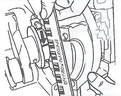
1. Place a piece of gauged Plastigage wire along the crankshaft journal.
Note. Observe the tightening torque of the screws.
To check the clearance in the main bearings, old bolts are allowed.
2. Install the crankshaft main bearing cap and tighten the mounting bolts in three steps:
- Tighten to 50 Nm.
- Using tool EN-45059, tighten to 45°.
- Using tool EN-45059, tighten to an angle of 15°.
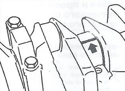
3. To turn away bolts of a cover of the radical bearing.
Note. When determining the gap on the scale, do not confuse the metric and English scales.
4. Measure the clearance in the crankshaft main bearing by comparing the width of the most flattened part of the gauge wire (arrow) with a measuring scale on the wire package.
Note. Observe the tightening torque of the screws. To check the clearance in the main bearings, old bolts are allowed.
1. Install the crankshaft main bearing cap to the cylinder block.
2. Tighten the cover bolts in three steps:
- Tighten to 50 Nm.
- Using tool EN-45059, tighten to 45°.
- Using tool EN-45059, tighten to an angle of 15°.
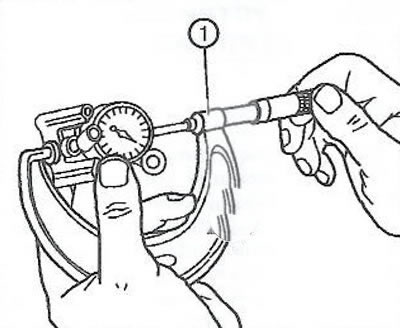
3. Calibrate the caliper (1) using a micrometer.
4. Using a bore gauge, measure the inner diameter of the main neck in three planes (A, B and C). Calculate the average value of the inner diameter: (A + B + C) / 3.
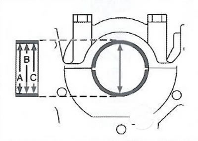
5. Using a micrometer, measure the outer diameter of the crankshaft main journal in two planes (I and II).
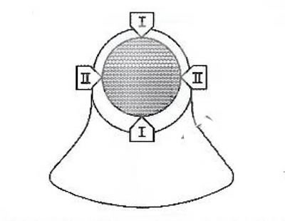
6. Calculate the average value of the outer diameter of the main journal: (I + II) / 2.
7. Calculate the main bearing clearance by subtracting the main journal outside diameter from the main bearing inside diameter.
Visitor comments