


Piston ring gap
1. Install the piston ring into the cylinder as shown in the figure and measure the gap in the lock using a set of flat feeler gauges (1).
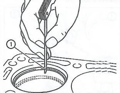
Compare the obtained results with the original values:
- compression ring lock: 0.25-0.40 mm;
- clearance in the oil scraper disk: 0.25-0.75 mm.
2. If the gap in the lock is greater than the permissible value, the piston ring must be replaced.
3. Measure the piston ring side clearance as shown in the figure.
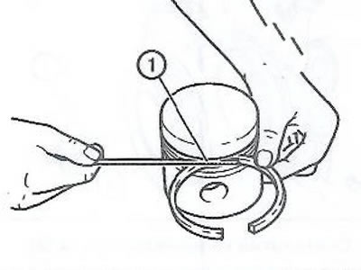
Compare the obtained results with the original values:
- compression ring side clearance: 0.25-0.7 mm;
- side clearance of oil scraper ring: 0.04-0.12 mm.
4. If the clearance exceeds the permissible value, replace the piston ring with a new one. If the clearance is still too large, replace the piston.
Clearance in connecting rod bearings
1. Install the bearing shells into the connecting rod and connecting rod cap.
2. Tighten the connecting rod cap bolts:
- Tighten the connecting rod cap bolts to 10 Nm.
- Tighten the connecting rod cap bolts an additional 60° using the EN-470-B tool.
- Tighten the connecting rod cap bolts an additional 15° using the EN-470-B tool.
3. Using a bore gauge, measure the inner diameter of the opening of the lower connecting rod head with the bearing shells installed at three points, as shown in Figure (1).
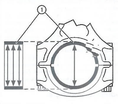
4. Calculate the average value of the inner diameter of the hole of the lower head of the connecting rod with the liners installed:
(Result 1 + Result 2 + Result 3): 3
5. Using a micrometer, measure the diameter of the crankshaft connecting rod journal in two planes between points 1-3 and 2-4.
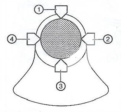
6. Calculate the average value of the crankpin diameter:
(Result 1 + result 2): 2.
7. Subtract the average crankpin diameter from the average crankpin bore diameter with the bearing shells installed to obtain the clearance between the crankpin and the connecting rod. The clearance should be 0.013-0.061 mm.
Visitor comments