
Cleaning
1. Remove any remaining sealant and gaskets or seals.
2. Clean all surfaces of the cylinder head with a non-corrosive solvent.
3. Blow out the oil passages in the cylinder head with compressed air.
4. Remove carbon and soot from the combustion chamber.
Visual check
1. Check the surfaces of the main bearings of the camshafts in the cylinder head for:
- Excessive wear and tear.
- Discoloration due to overheating.
- Deformations due to excessive wear.
If any defects are found, the cylinder head must be replaced. Do not bore or grind main bearings in the cylinder head.
2. Check the cylinder head for:
- Cracks, damage or spalling in the combustion chamber.
- Abrasive particles in oil channels (after removing these particles, flush the oil channels).
- Coolant leaks or damage to sealing surfaces (in the presence of coolant leaks, it is necessary to check the non-flatness of the contact surfaces of the cylinder head).
- Damage to contact surfaces.
- Burnt or eroded areas in combustion chambers.
- Cracks in exhaust ports and combustion chambers.
- External cracks in the channels of the cooling system.
- Blockages in the inlet and outlet channels.
- Blockages in the channels of the cooling system.
- Rust, damage or depressurization of plugs.
3. If the cylinder head is cracked or damaged, it must be replaced with a new one. Welding or patching is not allowed.
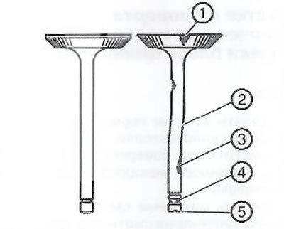
Checking the technical condition of valves
1. Clean the valves from soot and oil. Soot is removed with a stiff bristled brush.
2. Check the condition of the valves:
- Check valve surfaces for burns and cracks (1). If there are chips, replace the valve and check the corresponding cylinder area on the block head for damage.
- Check the straightness and absence of deformations of the valve stem (2). A deformed valve must be replaced with a new one.
- Check valve stem for wear (3).
- Check the groove on the valve stem for the installation of crackers for chips and wear (5). If defects are found, replace the valve with a new one.
3. Caliper (1) measure valve length (2).
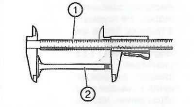
Note. All values are given in the section «Service data and specification» at the end of the chapter.
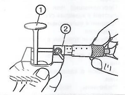
4. Using a micrometer (2) measure valve stem diameter (1). Write down the obtained values.
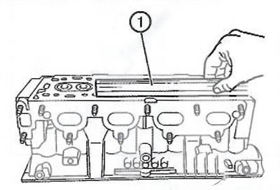
Checking the technical condition of the cylinder head
1. Check the flatness of the contact surface of the cylinder head using a straight edge (1).
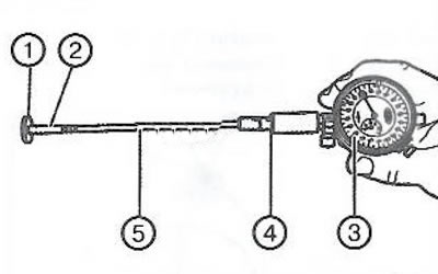
2. Using a dial gauge, measure the clearance between the stem and valve guide. To do this, assemble the EN-6216 dial indicator and EN-6216-200/300/400 components as follows:
- Install extension cord (5) on a support (4).
- Install a caliper (2) to extension cord (5).
- Install dial indicator (3) on a support (4) and set to a preset value of 1 mm.
- Install shim (1), as shown in the figure to align the indicator.
- Set the indicator to 0 by turning the dial.
- Carefully remove the shim (1).
3. Using a dial indicator with an inside gauge (1), measure the inner diameter of the valve guide (2) in various planes (3). Write down the obtained values.
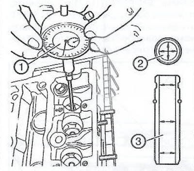
Subtract the value of the valve stem diameter from the average value of the inner diameter of the corresponding guide bushing to obtain the clearance value between the stem and guide bushing.
Visitor comments