


Severe engine overheating can lead to deformation of the cylinder head and disruption of the flatness of its mating surfaces.
Cleaning
1. Scrape off all traces of old gasket material and sealant from the mating surfaces of the cylinder head, being careful not to damage the surfaces.
The work will be made much easier by using a special softener, which should be used to soak the stuck deposits beforehand - ask in car accessory stores.
2. Remove all traces of scale from the walls of the water channels.
3. Using a stiff wire brush, thoroughly clean all accessible cavities and openings. If the channels are heavily contaminated, head cleaning should be entrusted to specialists.
4. "Run" each of the bolt holes with a tap of the appropriate size, removing corrosion products and traces of old sealant from the threads and restoring damaged threads. If you have access to a source of compressed air, blow out the holes, removing chips and small debris from them.
When using compressed air, remember to wear safety glasses!
5. Using solvent and a brass wire brush, clean the combustion chambers from carbon deposits.
6. Wash the head with solvent and dry it thoroughly. Using compressed air will significantly reduce the drying time and will guarantee the quality of cleaning of hard-to-reach cavities and holes.
Various types of carbon deposit removers, which make the cleaning process much easier, can be purchased at many car accessory stores. Remember that these types of products are usually chemically aggressive and should be used with appropriate precautions - strictly follow the manufacturer's instructions, usually on the container label.
7. On sOHC engines clean the valve actuator levers with solvent. Dry the components thoroughly with compressed air and store them in an organized manner.
8. Wash with solvent and dry the tappets/hydraulic valve lash adjusters.
Using compressed air will make the procedure much easier (don't forget to wear safety glasses).
9. Wash in solvent and thoroughly dry the valve springs, their plates and split lock crackers - try not to mix up the components.
10. Scrape off the bulk of the deposits that have formed on the valve surfaces, then use a wire attachment on an electric drill to finally clean the surfaces of the valve stems and plates - make sure that the valves are not mixed up.
Checking the status
Before deciding whether to machine the cylinder head, carefully examine its condition. After reviewing the material in this subsection, make a list of components that require special attention.
Cylinder head
1. Carefully check the cylinder head for signs of coolant leaks, cracks and other damage. A cracked head must be replaced. If you are not sure of the condition of the head, send it to a car service workshop for inspection. If repair is not possible, replace the defective head.
2. Using a flatness gauge and a blade-type feeler gauge, check the mating surface of the head for signs of deformation. If the flatness exceeds the permissible value according to the standards (see Specifications in Chapter Engines), the head must be sent to a mechanical workshop for turning.
One of the operating parameters of cylinder heads is their minimum permissible height (II) (from mating surface to mating surface), which must not be reduced during machining (see Specifications in Chapter Engines).
3. The valve stem must not protrude from the cylinder head by more than "I". For OHC 1.2 and 1.4 L engines, this value must not exceed 14.4 mm. The valve end face is not subject to machining. If the "I" dimension is exceeded, the cylinder head must be replaced.
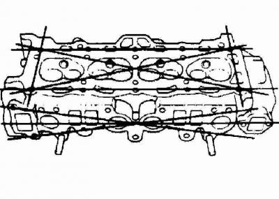
The degree of deformation of the cylinder head is assessed using the diagonals of each of the mating surfaces
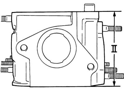
Cylinder head height measurement is taken from mating surface to mating surface
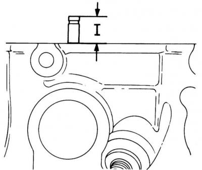
Measuring the height of the valve protrusion above the cylinder head
4. Check the condition of the valve seats in each combustion chamber. If cavities, cracks, or burnout marks are detected, the head should be subjected to special restorative repairs, the implementation of which is beyond the qualifications of the average amateur mechanic and should be entrusted to car service specialists (worn valve guides must first be replaced).
On diesel engines it is possible to replace the valve seats.
5. Using a special bore gauge, measure the inside diameter of the valve guide bushing. After removing the gauge from the bushing, measure it with a micrometer. Also measure the outside diameter of the valve stem. In order to determine the clearance of the valve seat in the bushing, subtract the result of the second measurement from the result of the first measurement. Compare the obtained data with the requirements of the Specifications in Chapter Engines.
When using a bore gauge, insert it to the middle of the bushing length, then move it up and down. Uneven resistance to movement of the gauge indicates the presence of taper in the bushing. If you are not sure when determining the condition of the components, do not hesitate to seek help from specialists.
6. Worn bushings are subject to replacement. Old bushings are knocked out into the combustion chambers using a drift. Before installation, new bushings should be cooled in a freezer, then pressed into the head bores on the camshaft side to the prescribed standard (see Specifications in Chapter Engines) level of protrusion (if the data on the guide bush protrusion height is not provided, please contact your Opel authorized service station for advice).
A sign of a weakened valve seat in the guide bushings is the appearance of blue smoke at the outlet of the exhaust system.
7. On diesel engines check for cracks and burnouts in the pre-chamber. Minor defects should not cause concern. Replacement of the chambers is required only in cases of deep burnouts, loss of the original shape or weakening of the fit in the head casting. If you are not sure about the condition of the pre-chambers, do not hesitate to contact specialists for help.
Valves
1. Carefully inspect the working surfaces of the valves for signs of uneven wear, deformations, cracks, cavities and traces of burnout. Assess the degree of operation of the valve stems. Check for cracks in the necks of the stems. Check the valves for bending by rotating them. Make sure there are no cavities and signs of excessive wear on the ends. Detection of any of the listed defects requires delivery of the valves for restoration to the auto service workshop.
Valve sections to be checked
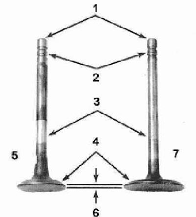
1 — Ends (shanks) rods
2 — Grooves for installing split lock crackers of plates
3 - Rods
4 - Working chamfers
5 - Exhaust valve
6 - Cylindrical part of the plate (belt)
7 — Inlet valve
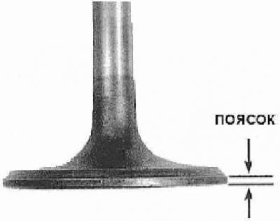
2. Measure the width of the cylindrical portion (belt) of the valve disc for each valve. If the width of the belt is less than that specified in the Specifications in Chapter Engines value, replace the valve.
The width of the cylindrical part (belt) of the valve plate must not be less than the value specified in the Specifications
Valve springs
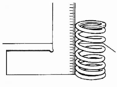
1. Assess the degree of wear of the end portions of each valve spring, check the springs for cavities. Using an angle gauge, determine the free length and check the end face of the valve springs. Compare the measurement results with the requirements of the Specifications in Chapter Engines, - if the spring is shorter than the lower permissible limit, it is sagged and must be replaced. Also check the forces developed by the springs for compliance with regulatory requirements (it is better to entrust this work to specialists at a car service workshop). If you are not sure about the condition of the springs, it would be better to replace them.
Measuring free length and checking valve spring end face
2. On SOHC petrol engines produced before September 1995. the exhaust valve spring seats are equipped with rotators that facilitate the free rotation of the valves in the guide bushings. By turning them manually, assess the condition of the rotators; if jerks or signs of sticking are detected, replace the defective components.
3. Check the spring plates and split lock crackers for cracks and signs of wear. Any parts in questionable condition should be replaced with new ones to avoid future defects.
Camshafts, valve lifters and rocker arm assemblies with axles
A description of the procedures for checking the status of the listed components is given in Section Removal, inspection and installation of valves. The condition of the camshaft bearing journals should be assessed before the head is sent to the workshop for valve maintenance. If there are any scratches, scoring or other mechanical defects on the journals, the head must be replaced regardless of the condition of the valve train components. When servicing an SOHC engine, the condition of the valve drive rocker arms with axles should also be checked.
Replace any defective components found.
Lapping valves
If the valve components are significantly worn, which is quite likely for an engine in need of major repair, assemble the valve assemblies, install them in their regular places in the head and proceed to performing valve maintenance procedures. If the external condition of the valves is found to be satisfactory, measure the diameters of their stems at several points with a micrometer. If a significant difference in the results is detected, the valve should be replaced.
To ensure reliable overlap of the valves into the combustion chambers during engine operation, they should be ground in during installation. In addition, grinding allows you to get rid of minor defects in the mating surfaces. The required smoothness of the seat surface after mechanical treatment can only be achieved using fine-grained lapping pastes. Before using coarse-grained pastes (if there is serious damage or burnout of the seats) consult with specialists - perhaps the only acceptable solution will be to replace the seat or valve.
1. Before you begin lapping the valves, place the head on a workbench with the surface mating with the block facing up.
2. Apply a small amount of lapping paste of the required grain size to the valve seat surface, then attach the suction cup of the lapping device to the outer surface of the valve plate. Using rotational movements, begin to lap the valve to the seat, lifting it from time to time to redistribute the paste. Installing a weak spring under the valve plate will help make the task easier. When using coarse-grained pastes, try to achieve a dull matte surface of the lapped parts. Having achieved the desired result, clean the surfaces from abrasive and repeat the lapping procedure using fine-grained paste.
3. Lapping can be considered complete when a continuous smooth matte ring appears on the working surfaces of the seat and plate. As soon as the required result is achieved, lapping should be stopped.
4. After finishing grinding all valves, remove all traces of abrasive and grinding paste with kerosene or solvent.
Visitor comments