
Removing
When working in the engine compartment, it must be borne in mind that the radiator fan can turn on independently when the engine is turned off and the ignition is on (position «II» ignition key). Due to the processes of heat removal taking place in the engine compartment, this can happen repeatedly. Therefore, if possible, when working in the engine compartment, turn off the ignition.
Do not forget that fuel is a highly flammable liquid! Observe all applicable fire safety precautions when working on power system components. Do not smoke, do not approach the work area with an open flame or an unprotected carrier. Do not service the system in a room equipped with natural gas-fired, pilot flame-equipped heaters (such as water heaters and clothes dryers). Do not forget that fuel is one of the carcinogens that contribute to the development of cancer. Try to prevent fuel from getting into open areas of the body - use protective rubber gloves, in case of accidental unforeseen contact, thoroughly wash your hands with warm water and soap. Clean up spilled fuel immediately and do not store fuel-soaked rags near open flames. Remember that the fuel injection system of models equipped with fuel injection is constantly under pressure. Relieve any residual pressure in the system before disconnecting fuel lines (see chapter Power supply systems, release and reduction of toxicity of exhaust gases). Wear safety goggles when servicing power system components. Keep a class B fire extinguisher handy at all times!
The air conditioning system path is also constantly under pressure, and therefore, before disconnecting the refrigeration lines, it is necessary to discharge the system in a specialized workshop.
All modern cars come standard with an SRS system, the main components of which are airbags. Always turn off the system before doing any work near the location of the SRS directional g-force sensors, in the area of the steering column or instrument panel, to prevent accidental deployment of airbags, which is fraught with serious injury.
The compilers of this Guide recommend removing the engine assembly with the transmission. The assembly of the unit is lowered down and removed from under the car, so you should take care of ways to securely fix the vehicle in a raised position.
Depending on the year of manufacture and equipment, vacuum hoses and hoses of the cooling system may have different routing routes. It is recommended to mark the connections with adhesive tape before dismantling them. The following describes the removal of the C14SE engine. Operations with other engines are carried out similarly.
1. Drive the car onto a flat, level surface with a sufficiently hard surface. Remove the hood (see chapter Body). Bring the front wheels into a straight line, remove the key from the ignition and lock the steering column.
2. Remove the battery (With. chapter Engine Electrical Systems).
Disconnecting the battery clears memory information such as DTC or audio system code. Disconnect the battery only when the ignition is off. Otherwise, the injection control unit may be damaged.
3. Remove the air filter with supply hose (see chapter Power supply systems, release and reduction of toxicity of exhaust gases).
4. Drain the coolant into a clean container.
5. Disconnect all cooling system hoses from the radiator. First loosen the clamps and slide them back.
6. Disconnect the fan motor connector and disconnect the wiring harness from the air intake sleeve.
7. Turn out fastening bolts of a sleeve of an air inlet and, having taken out it upwards from the holder, remove from a radiator.
8. Remove the throttle cable from the throttle body and move it aside (see chapter Power supply systems, release and reduction of toxicity of exhaust gases).
9. Remove all vacuum hoses from the throttle body.
10. Remove the vacuum hose from the brake booster.
Disconnecting the vacuum hose from the brake booster
11. Separate sockets of injectors and take a plait of electroconducting aside.
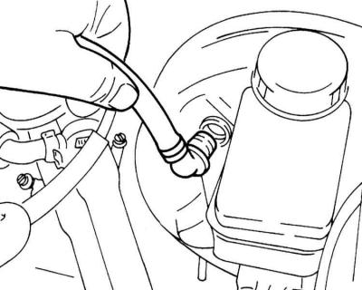
12. Disconnect the coolant hoses from the expansion tank and remove it.
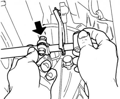
13. Disconnect the heater hoses from the nozzles on the bulkhead of the engine compartment.
Fastening of heater hoses
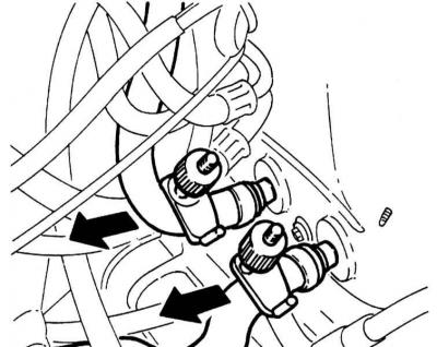
14. Remove the bracket from the clutch cable and disconnect the cable from the clutch lever.
Clutch cable attachment and reversing light switch connector
15. Disconnect the reversing light switch connector (arrow on the left in the illustration).
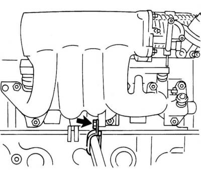
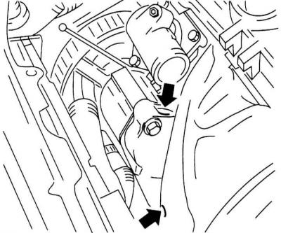
16. Mark the supply and return fuel hoses so as not to confuse them during assembly. Clamp the hoses with clamps. Disconnect the holder of fuel hoses at the inlet pipeline and remove them. Collect escaping fuel with a rag.
Fastening of the holder of fuel hoses
17. Disconnect the speedometer from the gearbox.
18. Mark with a tape all electroconducting going to the engine and disconnect it.
19. When the car is equipped with a power steering system, loosen the tension of the V-shaped belt and remove it (see chapter Vehicle settings and routine maintenance).
20. If equipped, unscrew the fastening bolts and remove the power steering pump from the holder on the cylinder block and, without disconnecting the hoses from the pump, tie it up with wire so that it does not interfere with further disassembly and that the hoses are not stretched.
Fasteners for power steering pump
21. Mark the position of the respective front wheel relative to its hub so that the balanced wheel can then be returned to its original position. Loosen the wheel bolts with the vehicle on the ground. Jack up the front of the car, place it on jack stands and remove the front wheel.
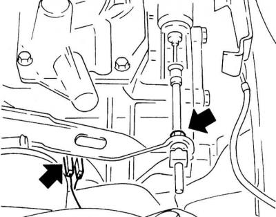
22. Remove the shift lever from the stem on the gearbox. To do this, loosen the clamp on the lever. Pre-mark both parts so that they can be installed in their original position during assembly.
Clamp on gear lever
23. Disconnect the electrical wiring from the generator and starter (see chapter Engine Electrical Systems).
24. Disconnect the intake pipe from the exhaust manifold, remove it from the holders and tilt it to the side.
25. Take out on the right and at the left from rotary fists spherical support. Loosen the clamping bolts first.
26. Disconnect from a body forward cross-section levers.
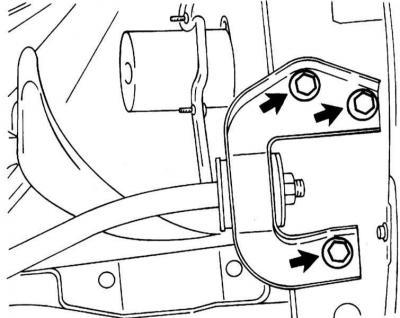
27. Give bolts of fastening and remove the holder of draft of a forward suspension bracket from a cross beam of a forward subframe together with draft and the anti-roll bar.
Bolts of fastening of the holder of draft of a forward suspension bracket
28. Knock out both drive shafts from the gearbox housing.
29. Place a jack under the engine and slightly raise the power unit. You can also use a lifting device by hooking it onto the lifting eyes of the engine. Raise the engine to relieve both of its upper mounts.
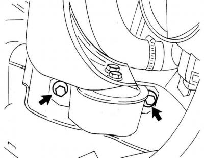
30. Give fastening bolts and remove blocks of depreciation of the engine from a longitudinal beam of a forward frame and from the engine. On the accompanying illustration shows the front left damping block on vehicles without power steering or K / V systems.
Bolts of fastening of the forward left block of depreciation
31. Check that all hoses, wiring and other lines have been disconnected from the engine.
32. Carefully lower the engine with the gearbox out of the engine compartment.
33. Disconnect the gearbox from the engine (see chapter Manual 5-speed gearbox or Automatic 4-speed transmission).
Installation
1. Check engine mounts, coolant hoses, oil and fuel hoses for cracks or other damage and replace as necessary. Carefully tap the threads in the holes in the front frame beam to remove any remaining sealant.
2. Check up a thickness of a conducted disk of coupling, and also a condition of frictional overlays. In case of significant wear or high mileage, replace the driven disk as a set. If the clutch release bearing makes noise when the clutch pedal is depressed, replace the bearing.
3. Clean the clutch release bearing and lubricate the splines with a thin coat of MoS2 grease.
4. Connect the gearbox to the engine (see chapter Manual 5-speed gearbox or Automatic 4-speed transmission).
5. Using lifting equipment, carefully place the engine with gearbox into the engine compartment. Align the engine with the supports and tighten the mounting bolts.
6. Rock the engine in different directions.
7. Having previously cleaned the threads of the engine damping block mounting bolts with a brush and lubricated it with OPEL-90 167 347/15 10 sealant, tighten them with the required forces.
8. Insert both drive shafts into the gearbox housing until they stop.
9. Reinstall the wishbones, links and stabilizer (see chapter Suspension and steering).
10. Connect generator and starter wiring (see chapter Engine Electrical Systems).
11. Install the exhaust system in rubber mounts and secure with bolts 25 Nm to the exhaust manifold.
Use a new gasket.
12. Put the gearshift lever on the stem and align the marks made during removal.
13. Check gearshift adjustment (see chapter Manual 5-speed gearbox or Automatic 4-speed transmission).
14. Reinstall the front wheels and align the marks made when removing them. Screw on the wheel bolts. Lower the vehicle to the ground and tighten the bolts crosswise with force 110 Nm.
15. Fix a shaft of a speedometer on a transmission.
16. Attach the clutch cable, install the brackets.
17. Connect the electrical wiring of the reversing lamp.
18. Put the heater hoses on the fittings on the bulkhead of the engine compartment and fix the hoses with clamps.
19. Connect fuel hoses according to the marking put earlier and fix them collars. The fuel supply hose must be pushed far enough onto the corresponding pipe. Make sure that the clamps do not touch adjacent elements. Attach the fuel hoses to the holders at the exhaust manifold.
20. Put a vacuum hose on the amplifier of brakes and check up reliability of connection.
21. Attach the coolant reservoir to the bulkhead of the engine compartment. Connect the cooling system hoses and secure with clamps.
22. Connect the engine wiring harness connectors.
23. Connect sensors of temperature and pressure of motive oil.
24. Connect the injector connectors and secure the wiring harness.
25. Attach the throttle actuator to the throttle body and check its adjustment (see chapter Power supply systems, release and reduction of toxicity of exhaust gases).
26. Attach the air intake funnel to the holders on the radiator.
27. Connect a socket of the electric motor of the fan and the thermostat. Attach the wiring harness.
28. Connect the lambda probe connector.
Wiring should be laid as far away from the fan as possible.
29. Attach the upper and lower hoses to the radiator and secure them with clamps.
30. Install the air supply hose and air filter. At the same time, clean the air filter and its housing, if necessary, replace the filter (see chapter Power supply systems, release and reduction of toxicity of exhaust gases).
31. If equipped, attach the power steering pump to the holder. Put on the V-belt (see chapter Vehicle settings and routine maintenance).
32. Connect the negative battery cable.
Connect the battery only when the ignition is off. Otherwise, the injection control unit may be damaged.
33. Check the quality of the coolant and fill it into the cooling system (see chapter Vehicle settings and routine maintenance).
34. Let the engine cool down and check the coolant level. Check all hose connections for leaks.
35. Check and, if necessary, correct the oil level in the gearboxes.
Visitor comments