


Contents: Removal ⬇ Installation ⬇
Note: A winch and lifting device will be required to perform this job. If the torque converter is removed from the transmission (even partially), there may be a significant fluid leak. To prevent this, disconnect the engine from the transmission, carefully support the torque converter by pressing it firmly against the transmission. If the transmission needs to be removed at some point, secure the torque converter by bolting a metal strip across the mating surface of the clutch housing.
Removal
1. Disconnect the negative cable from the battery.
2. Remove the hood (Section 11).
3. Apply the handbrake, then jack up the front of the vehicle and support it on axle stands.
4. Drain the cooling system, remove the radiator and transmission fluid cooler hoses (models with automatic transmission), as described in Section 3.
5. Drain the engine oil as described in Section 1, remove and discard the oil filter.
6. Remove the air filter (or air filter cover), filter line, carburetor heater block or throttle body (depending on the model), guided by Sections 4A or 4B, if necessary. On carbureted models, disconnect the warm air hose from the air heater chamber on the exhaust manifold and from the air cleaner, remove the hose. On models with an automatic transmission, disconnect additional electrical wiring, hoses, etc. from the carburetor, as described in Section 4A.
7. Remove the generator as described in Section 5.
8. On models with power steering, remove the hydraulic pump as described in Section 10.
9. Disconnect the brake booster vacuum hose from the intake manifold.
10. Disconnect the cable from the throttle lever and bracket on the carburetor or intake manifold, depending on the model.
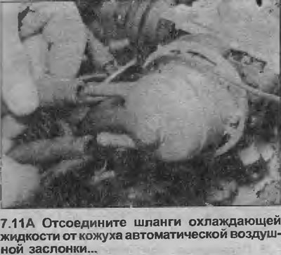
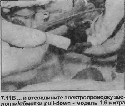
11. On carbureted models, disconnect the coolant hoses from the automatic choke housing, and disconnect the wiring from the automatic choke heater and the pull-down choke coil (see illustrations). Also disconnect the heater block vacuum line from the carburetor.
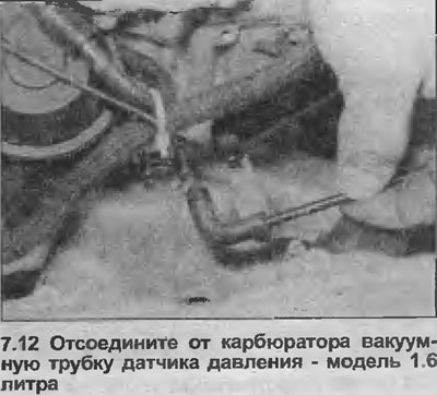
12. Disconnect the vacuum tube of the pressure sensor from the carburetor (see illustration).
13. Remove the coolant hoses from the intake manifold and/or throttle body, depending on model.
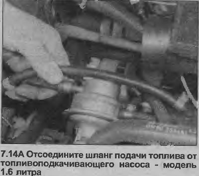
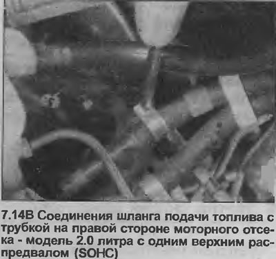
14. Disconnect the fuel supply hoses from the fuel lift pump and vapor separator on carbureted models, or from the fuel lines on the right side of the engine compartment on other models. Plug the open ends of the lines and hoses to prevent dirt from entering and fuel from leaking (see illustrations).
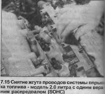
15. Disconnect all related wiring and connectors, remove the fuel injection system wiring harness. Pull the wiring harness cover, squeeze the wiring connector retaining clips to release the cover from the fuel injectors (see illustration).
16. Disconnect the heater coolant hoses from the coolant oil passage at the rear of the cylinder block.
17. Disconnect the electrical wiring from the following components (where are they applied):
- a) Starter
- b) Distributor (note the position of the high voltage wire)
- c) Oil pressure sensor
- d) Oil temperature sensor
- e) VARG sensor
- j) Oil level sensor
- g) Knock sensor
- h) Coolant temperature sensor
- i) Temperature indicator sensor
18. Perform a final check to ensure all relevant hoses, pipes and wires are disconnected and not connected to the engine.
19. Remove the front section of the exhaust system as described in Section 4C.
20. Unscrew and remove the clutch housing protective cover (see illustration).
21. Remove the clutch (depending on the model), as described in Section 6. On automatic transmission models, before removing the torque converter, use chalk or a felt-tip pen to mark its position relative to the drive plate. See the Note at the beginning of this Chapter and for more information, see. Section 7B.
22. Remove the crankshaft pulley. Some pulleys are attached with four bolts that need to be loosened with a socket wrench. Loosen and remove all four bolts one at a time. On other engines, the pulley is attached with a single bolt that also secures the crankshaft sprocket. On manual transmission models, if the engine is in the car, the crankshaft can be locked from turning by engaging 1st gear and pressing the brake pedal. Alternatively, insert a large screwdriver through the opening in the clutch housing cover into the teeth of the flywheel (or drive disc, on models with automatic transmission). The easiest way to get to the crankshaft pulley is through the arc of the right wheel, having first removed it.
23. Attach a winch to the engine lifting brackets on the cylinder head and lift the engine slightly.
24. Loosen and remove two of the three upper engine-to-transmission mounting bolts accessible from the engine bay, leaving one in place.
25. Unscrew the right engine mounting bracket from the body and from the cylinder block, remove the mounting bracket.
26. Loosen and remove the four lower engine-to-transmission mounting bolts.
27. Support the transmission with a jack and a block of wood underneath. Remove the remaining upper transmission mounting bolt.
28. Manipulate the engine as necessary to separate it from the transmission. Note that the transmission is located on pins in the cylinder block.
29. Carefully lift the engine out of the vehicle, being careful not to damage any components in the engine compartment.
30. With the engine removed, the transmission can be supported by placing a board between the clutch housing and the front suspension lower frame. Then remove the jack from under the transmission.
Installation
Note: New left and right engine/transmission mount to body bolts must be used during installation.
31. Using an M10x1.25 tap, clean the threads in the torque converter holes and prepare new bolts before assembly.
32. Support the transmission with a jack, remove the board between the clutch housing and the lower frame.
33. Support the engine with a winch or lifting device and slowly lower it into place in the engine compartment.
34. Connect the engine and transmission together, making sure that the transmission fits over the pins in the engine block. Then install the three upper engine-to-transmission bolts.
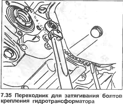
35. Tighten all nuts and bolts to the specified torque. When tightening the torque converter to drive plate bolts, a special adapter will be required (see illustration).
36. If the clutch is bolted to the flywheel, make sure the transmission does not hang on the input shaft.
37. Install the four lower engine to transmission mount bolts, but again do not tighten them completely at this stage.
38. Install the right engine mounting bracket to the cylinder block, tighten the mounting bolts with the specified tightening force Specifications.
39. Moving the engine and transmission as necessary, install the new right engine mount bracket to body bolts, then tighten them to the specified torque Specifications.
40. Tighten all engine-to-transmission mounting bolts to the specified tightening torque Specifications, then disconnect the lifting device and winch from the engine, remove the tom from under the transmission.
41. Install the protective cover of the transmission clutch housing.
42. Install the clutch as described Section 6.
43. Install the front part of the exhaust system as described in Section 4C.
44. Install the crankshaft pulley in the reverse order of removal described earlier in point 22. Tighten the mounting bolts with the tightening force specified Specifications.
45. Lower the car to the ground.
46. Install all relevant wires, tubes and hoses, etc. in the reverse order of removal described earlier.
47. Where applicable, install the power steering pump, tighten the pump drive belt, bleed the hydraulic circuit as described in Section 10.
48. Install the generator and tension the drive belt as described in Section 5.
49. Install the air cleaner components according to Sections 4A or 4B, if necessary. On carbureted models, reconnect the warm air hose to the air preheater chamber on the exhaust manifold.
50. Install a new oil filter if you have not already done so), fill the engine with oil as described in Section 1.
51. Install the radiator, fill the cooling system as described in Section 3.
52. Install the hood as described in Section 11.
53. Connect the negative battery cable.
54. Next, proceed to Chapter 37.
Visitor comments