


Note: A winch and lifting device will be required to complete this job.
Removal
1. Proceed as described in Chapter 7, items 1-18 inclusive.
2. Working in the engine compartment, remove the gear selector mechanism as described in Sections 7A and 7B, depending on the model.
3. On manual transmission models, remove the retaining clip, then pull the clutch cable off the release lever, if necessary, push the release lever back toward the bulkhead to allow the cable to disconnect. On automatic transmission models, disconnect the shift cable from the control lever, then either unscrew the cable bracket or release the cable from the bracket. In either case, move the cable retainer away from the bracket on the transmission case, then move the cable and secure it to the side, taking note of the direction.
4. Disconnect the wiring harness from the reverse light switch, which is located on the front of the manual transmission housing, above the left mounting bracket. On automatic transmission models, disconnect the transmission wiring harness by disconnecting the five connectors from the various switches, coils, and sensors. Release the wiring harness from any brackets or other fasteners to the vehicle.
5. Where applicable, remove the automatic transmission breather hose from under the battery bracket. Disconnect the oxygen sensor wiring, if applicable.
6. Unscrew the mounting sleeve, disconnect the speedometer drive cable from the transmission.
7. Loosen the mounting nut and disconnect the ground strap from the transmission end plate.
8. Make a final check to ensure all relevant hoses, pipes, wires, etc. are disconnected and not connected to the engine and transmission.
9. Proceed as described in Chapter 7, points 19 and 22.
10. Disconnect the inner ends of the drive shafts from the differential, following the appropriate steps in Section 8. Expect some oil to leak when disconnecting the drive shafts from the differential, so plug the holes to prevent further oil loss and dirt from getting in. Secure the drive shafts with wire or twine - do not allow them to hang by their own weight.
11. Attach a winch to the engine lifting brackets on the cylinder head, lift the engine slightly.
12. Remove the left transmission bracket by unscrewing the two bolts securing the rubber cushion to the car and body, three bolts securing the mounting bracket to the transmission (see illustration).
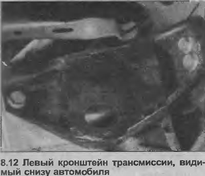
13. Unscrew the right engine mounting bracket from the body and from the cylinder block, remove the mounting bracket.
14. Working underneath the vehicle, loosen and remove the two nuts securing the rear engine/transmission mount to the subframe and the three bolts securing the mounting bracket to the transmission, then remove the mounting bracket (see illustrations).
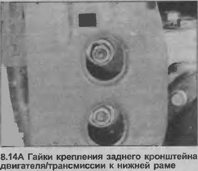
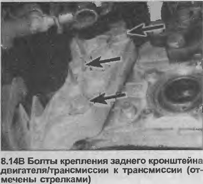
15. If necessary, gently rock the engine/transmission assembly across the engine bay to allow the assembly to come out vertically. Be careful not to damage any components in the engine bay.
Separation
16. Once the engine/transmission assembly is removed, set it on blocks placed in a workbench or on a clean area of the workshop floor.
17. Clean the assembly from dirt, use kerosene or water solvent and a hard brush.
18. Unscrew and remove the protective cover of the transmission clutch housing.
19. Check that the engine and transmission are securely supported, then loosen and remove the engine-to-transmission mounting bolts.
20. Carefully remove the transmission from the engine. Be careful that the transmission does not hang on the input shaft when it is connected to the clutch friction disc. Note that the transmission is located on pins placed in the cylinder block.
21. On models with automatic transmission, unscrew the protective cover of the clutch housing (three bolts), then before unscrewing the torque converter, use chalk or a felt-tip pen to mark its position relative to the drive disk.
Note: If the torque converter is removed from the transmission (even partially), there may be a significant fluid leak. To prevent this, disconnect the engine from the transmission and carefully support the torque converter by pressing it firmly against the transmission. If the transmission is to be removed at a later date, secure the torque converter by bolting a metal strip across the mating surface of the clutch housing. With a wrench on the crankshaft pulley/sprocket bolt, rotate the crankshaft until the first bolt appears, then use a screwdriver or similar to pinch the teeth of the drive plate ring gear to prevent it from rotating when the bolt is loosened. Loosen and remove the three bolts in turn.
Compound
22. Before installation, check that the two bolts securing the left transmission rubber mount to the vehicle body are screwed freely into their threaded holes. If necessary, renew the threads with an M10x1.25 mm tap.
23. Where necessary, if the clutch assembly is removed from the flywheel, it is easier to install after the transmission is installed.
24. On models with automatic transmission, if fluid has been spilled from the torque converter, be careful to fill it to the maximum possible level. Wipe the converter bushing to prevent damage to the transmission input shaft seal and ensure that the converter is properly engaged with the pump shaft.
25. If the transmission has been replaced, clean the passages of the auxiliary transmission fluid cooler. Opel recommends using low-pressure compressed air, but great care must be taken not to distort the radiator.
26. Be very careful. All components must be absolutely clean, make sure that no dirt gets into the system.
27. Using an M10x1.25 tap, clean the threads in the torque converter holes and prepare new bolts for assembly.
28. Tighten all nuts and bolts to the torque specified in the Specifications.
29. Be guided also Chapter 7, points 35 and 36.
30. Carefully connect the transmission to the engine (the clutch housing should be located on the pins in the cylinder block), then install and tighten the engine-to-transmission mounting bolts to the specified tightening torque Specifications.
31. Install the transmission clutch housing protective cover.
Installation
32. Working underneath the vehicle, attach the rear bracket to the transmission. Use new blocks under the bolt heads and tighten the bolts to Specifications.
33. Install the two bolts securing the rear engine/transmission bracket to the subframe, but do not tighten completely at this stage.
34. Install the right engine mounting bracket to the cylinder block, tighten the mounting bolts to the specified tightening torque Specifications.
35. Install the new right engine mount bracket to body bolts, but do not tighten them fully at this stage.
36. Install the left bracket to the transmission, tighten the mounting bolts with the specified tightening force Specifications.
37. Install new bolts for the left transmission mounting bracket to the body and tighten them to the specified tightening torque Specifications.
Material copied from the portal (OpelBook)
38. Tighten the right engine mount bracket to body bolts and the rear engine/transmission mount bracket to subframe bolts to the specified tightening torque Specifications then disconnect the lifting device and winch from the engine
39. Where necessary, the clutch can now be installed, the input shaft of the transmission should be engaged with the hub of the friction disc of the clutch (see section 5).
40. Connect the inner ends of the drive shafts to the differential, following the relevant points in Section 8, using new thrust washers.
41. Install the front section of the exhaust system as described in Section 4C.
42. Install the crankshaft pulley by reversing the removal procedure described in Chapter 7, point 22, and tighten the mounting bolts with the tightening force specified Specifications.
43. On models with automatic transmission, connect the wires to the various switches, coils and sensors. Replace the transmission saloon hose and oxygen sensor (if used).
44. Connect the transmission ground strap, tighten the fastening nut.
45. Lower the car to the ground.
46. Connect the speedometer drive cable to the transmission, tighten the mounting sleeve.
47. Connect the reversing light wiring.
48. On manual transmission models, attach the clutch cable to the bracket on the transmission case, then connect the cable to the release lever and adjust it as described in Section 6.
49. Install the gear selector mechanism as described in Section 7A.
50. Proceed as described in Chapter 7, items 41-52 inclusive.
51. Top up the transmission fluid level as described in Sections 7A and 7B.
52. Finally, adjust the shift cable and fill the transmission with fluid (see above).
53. Connect the negative battery cable.
54. Next, proceed to Chapter 37.
Visitor comments