
Removing
Do not forget that fuel is a highly flammable liquid! Observe all applicable fire safety precautions when working on power system components. Do not smoke, do not approach the work area with an open flame or an unprotected carrier. Do not service the system in a room equipped with natural gas-fired, pilot flame-equipped heaters (such as water heaters and clothes dryers). Do not forget that fuel is one of the carcinogens that contribute to the development of cancer. Try to prevent fuel from getting into open areas of the body - use protective rubber gloves, in case of accidental unforeseen contact, thoroughly wash your hands with warm water and soap. Clean up spilled fuel immediately and do not store fuel-soaked rags near open flames. Remember that the fuel injection system of models equipped with fuel injection is constantly under pressure. Relieve any residual pressure in the system before disconnecting fuel lines (see chapter Power and exhaust systems). Wear safety goggles when servicing power system components. Keep a class B fire extinguisher handy at all times!
The air conditioning system path is also constantly under pressure, and therefore, before disconnecting the refrigeration lines, it is necessary to discharge the system in a specialized workshop.
All modern cars come standard with an SRS system, the main components of which are airbags. Always turn off the system before doing any work near the location of the SRS directional g-force sensors, in the area of the steering column or instrument panel, to prevent accidental deployment of airbags, which is fraught with serious injury.
The compilers of this Guide recommend removing the engine assembly with the transmission. The assembly of the unit is lowered down and removed from under the car, so you should take care of ways to securely fix the vehicle in a raised position.
1. Drive the car onto a flat, level surface with a sufficiently hard surface. Remove the hood (see chapter Body). Bring the front wheels into a straight line, remove the key from the ignition and lock the steering column.
2. On diesel models 1.7 l remove the heater control unit from the left side of the battery support tray. Remove the battery from the tray (see chapter Engine electrical equipment).
3. Support the rear wheels with wheel chocks, firmly apply the parking brake. Loosen the front wheel bolts. Jack up the front of the car and place it on jack stands. Remove the front wheels. If equipped, remove the crankcase protection.
4. If the engine is removed for the purpose of overhaul, drain the oil from it and remove the oil filter (see chapter Current service).
5. Perform the following procedures (see chapter Power and exhaust systems):
- Remove the air cleaner assembly with air ducts;
- Remove a reception pipe and an average part of system of release of the fulfilled gases;
- Disconnect the lines of the power system;
- On diesel models 1.7L DOHC disconnect the fuel lines from the injection pump, - on other diesel models, disconnect the fuel supply and return lines from the fuel filter;
- Disconnect and move aside the throttle cables and (with appropriate equipment) tempostat cable - try to remember the routes for laying the cables;
- Disconnect the brake booster servo vacuum hose - try to remember the route of the cable;
- On diesel models release the mounting clamps, disconnect and take aside the air sleeves connecting the turbocharger to the intercooler and the intercooler to the inlet pipeline;
- Disconnect the hose from the vacuum pump and the EGR valve, - take the hose to the side;
- On petrol models Disconnect the fuel tank vent valve hose from the throttle body.
6. On petrol models remove the front bumper (see chapter Body).
7. On diesel models 1.7 l SOHC release the fixing and disconnect from the branch pipes the oil cooler hoses laid between the cylinder block and the radiator.
8. Acting in accordance with the instructions given in Chapter Cooling, heating systems do the following:
- Empty the cooling system;
- Loosen the clamps and remove the upper and lower coolant hoses from the radiator. Disconnect all hoses of the cooling path from the engine;
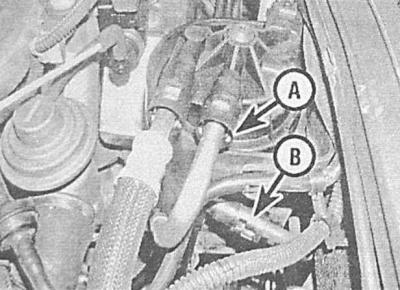
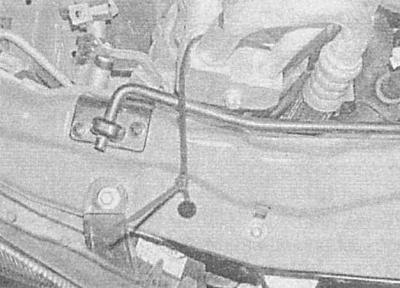
- On the rear partition of the engine compartment, disconnect the hoses of the cooling path from the heater heat exchanger: squeezing the clamp, slide the ring forward and release the hose from the fitting connector - note that black rings are used in the upper hose connections.
- On air-conditioned models disconnect from the engine and take aside the lines of the refrigeration path;
- Using suitable bolts or rods through the holes in the support brackets, fix the radiator/condenser of the A/C system in place.
9. Disconnect the wiring:
Gasoline engines
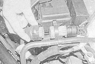
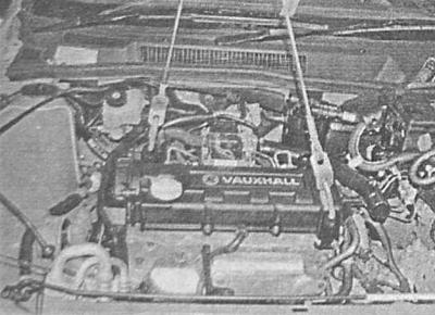
1. Turn the circlip and disconnect the large multi-pin engine wiring connector at the front of the engine compartment relay mounting block.

2. Connectors of all other harnesses of the engine compartment connected to the main braid of electrical wiring.
Diesel engines
1. Turn the circlip and disconnect the large multi-pin engine wiring connector at the front of the engine compartment relay mounting block.
2. Turn out bolts and disconnect a loop from the terminal lug of a positive wire of the battery and two loops from a lug of a negative wire.
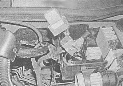
3. Open the cover of the mounting block located in the left rear corner of the engine compartment and remove the green relay and fuse with their pads.
4. On 1.7L DOHC engines lift the lever and disconnect from the engine control unit installed above the inlet pipeline (ECM) extreme rear connector.
5. Release the wiring harnesses from all intermediate clips and place them on top of the engine.
6. On 1.7L SOHC engines disconnect the wiring from the following components:
- EGR valve;
- coolant temperature sensor (ECT);
- Electronic control module (ECM), - remove the locking element;
- glow plugs;
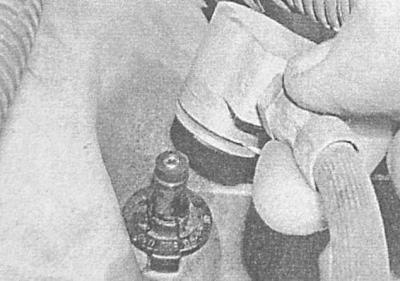
- crankshaft position sensor (CKP);
- Oil temperature sensor;
- Sensor-switch of reversing lights.
7. Finally, unscrew the three bolts securing the electrical wiring to the rear of the timing cover and take the wiring away from the engine, also release the wiring from the clamps on the front of the cylinder block - take all the harnesses away from the engine.
10. Drain gear oil/ATF.
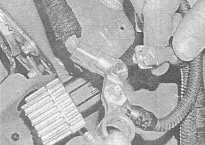
11. On models with manual transmission clamp the hydraulic hose of the clutch path drive with a clamp immediately behind the nipple connector (see chapter Clutch and drive shafts). Using a screwdriver, gently pry off the retaining clip of the connector and disconnect the hose from the clutch dome.
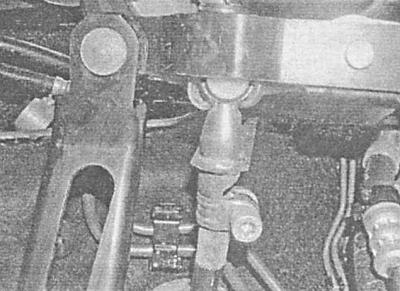
12. Disconnect the shift rods/selector cable from the transmission (see chapter Manual transmission or automatic transmission).
13. On models with AT Disconnect from transmission electroconducting and hoses of a path of cooling ATF.
14. Attach rigging to the lifting eyes and hang out the power package.
15. Remove both drive shafts (see chapter Clutch and drive shafts).
16. Remove the front subframe (see chapter Suspension and steering).
17. Once again make sure that all communication lines and nothing interferes with the removal of the power unit from the engine compartment.
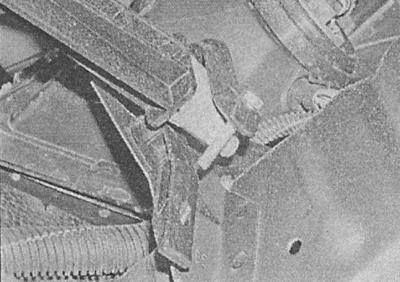
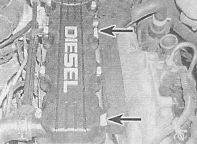
18. Mark the mounting positions of the powertrain suspension mount components and transmission adapter plate. Turn out three bolts of fastening of the right support of the engine to an arm on the block of cylinders, also give three bolts of fastening of a support to a body element. Remove the three bolts securing the left support to the transmission adapter plate. On models equipped with air conditioning disconnect the electrical wiring, give the fasteners, remove and tie up the K / V compressor to the front panel. If necessary, release the hoses of the refrigeration path from the clamps behind the right suspension bracket of the power unit.
Do not open the refrigeration path under any circumstances!
19. Place a trolley jack under the engine. Lower the power unit, being careful not to pinch the hoses or wiring or damage the radiator/fan. If necessary, seek the help of an assistant - the unit may have to be tilted slightly to remove it from the opening of the engine compartment. Fix the unit on a jack.
20. Disconnect the lifting rigging and roll out from under the car the jack with the power unit attached to it.
Engine separation from transmission
Models with manual transmission
1. After removing the power package, lay it on wooden blocks on a workbench or on a clean garage floor.
2. On models with stamped steel pallets, remove the mounting bolts and remove the flywheel cover from the transmission case.
3. Remove the starter (see chapter Engine electrical equipment).
4. Make sure the weight of the power package is evenly distributed on the props. Turn out bolts of fastening of transmission to the engine, - try to remember an order of installation of all bolts and brackets fixed by them.
5. Carefully separate the transmission from the engine, preventing the input shaft from hanging on the clutch.
6. Remove the loose-fitting guide bushings and store them in a safe place.
Models with AT
1. After removing the power package, lay it on wooden blocks on a workbench or on a clean garage floor.
2. Remove the starter (see chapter Engine electrical equipment).
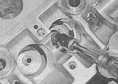
3. In order to provide access to the torque converter mounting bolts, release the rubber cover from the sump flange (lids). Unscrew the bolt to which there is access, then, turning the crankshaft by the pulley bolt, unscrew all the other bolts securing the torque converter to the drive disk in turn (on engines 1.4, 1.6 and 1.8 l three fixing bolts are used, on engines 2.0 l - six).
During assembly, the bolts must be replaced without fail.
4. To prevent the torque converter from falling out when the transmission is separated, push it along the shaft deep into the crankcase.
5. Then proceed in the order described above (see Models with manual transmission).
Connecting the engine to the transmission
All models
Proceed in reverse order to disconnect the power unit.
Installation
1. Having oriented in the right way, start the power unit under the engine compartment of the car. Connect the rigging to the engine lifting eyes. Drive the block into the engine compartment and position it in such a way that it becomes possible to install the suspension supports of the power unit. Install the supports and lightly tighten the fasteners for now.
2. To shrink on the supports, move the unit in different directions.
3. Lower the machine and tighten its suspension brackets to the required torque. Disconnect the lifting rigging and remove the trolley jack from under the vehicle.
4. Further installation is carried out in the reverse order of dismantling. Pay attention to the following points:
- Tighten all fasteners to the required torque (see Specifications to the relevant Chapters of the Manual);
- Follow the correct laying of the wiring harnesses and the reliability of fastening their contact connectors. Make sure that the wiring is laid at a sufficient distance from heat sources;
- Restore the original connection of all hoses and tubes - make sure that the fastening clamps are tightened securely;
- On models with manual transmission, check the adjustment of the gear shift actuator, if necessary, make the appropriate adjustment (see chapter Manual transmission);
- Recharge the cooling system (see chapter Cooling, heating systems);
- Fill the transmission with fresh oil (RKPP) or ATF (AT) / correct the hydraulic fluid level (see chapter Current service);
- Adjust throttle cables (see chapter Power and exhaust systems) And (with appropriate equipment) tempostat;
- After the first start of the engine, carefully inspect the entire surface of the power unit and bulkheads of the engine compartment for signs of the development of leaks of working fluids.
If the engine has been overhauled, before starting it, see Trial run and running-in of the engine after overhaul.
Visitor comments