
Removing
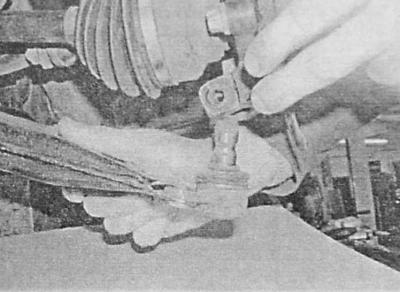
1. Remove the wheel cap and wheel nut protection cap. Remove the lock pin securing the castellated hub nut.
On some models, the disc cap is attached with wheel bolts. In this case, the bolts should be loosened, then raise the car above the ground, remove the cap, screw the bolts into place, lower the car to the ground, and only after that proceed with releasing the hub nut.
2. Loosen the castellated hub nut with a socket wrench equipped with a long collar. The hub is blocked from turning by means of a metal bar (1).
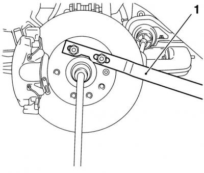
The hub nut can also be released after removing the wheel - the hub will have to be fixed from turning with a bar fixed with two wheel bolts, or a mount tucked between the bolts.
3. Loosen the nuts of the corresponding front wheel, jack up the front of the car and place it on jack stands. Remove the wheel. Drain gear oil/ ATF (see chapter Current service).
4. Finally remove the hub nut together with the washer.
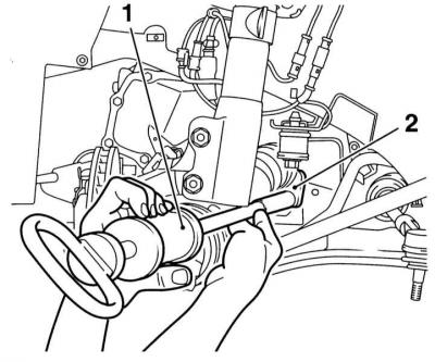
5. Give a nut of fastening of a tip of steering draft and by means of a special puller release the last from a rotary fist.
6. Turn out a bolt of fastening of a basic arm of a flexible brake hose to a rack of a suspension bracket, release a hose from an arm.
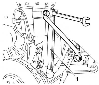
7. Holding the hinge pin with an open-end wrench by the flats, give the vertical link mounting nut (1) anti-roll bar to suspension strut. Pull the rod away from the rack.
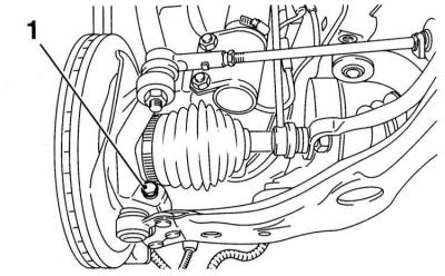
8. Turn out a bolt of a collar of fastening of a spherical support to a rotary fist, — pay attention that the bolt is developed by a head forward on the car.
9. Use a large screwdriver or chisel to wedge the ball joint yoke.
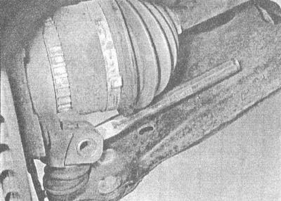
10. While moving the suspension arm down, release the shank of the ball joint pin from the mounting collar. Take the rack to the side and release the lever - try not to damage the rubber boot of the ball joint.
11. Pulling the hub outward, remove it from the drive shaft stub. If the hub cannot be removed, to protect the threads, temporarily screw the hub nut onto the shaft and pull the knuckle outward while tapping the trunnion with a hammer through a suitable soft metal drift. Alternatively, you can use a special puller bolted to the hub with wheel bolts.
12. Take aside the rack and lay the free end of the drive shaft on a suitable support, preventing it from hanging on the inner CV joint.
13. If equipped, remove the crankcase protection.
14. Prying the CV joint with a special fork, overcoming the resistance of the expandable retaining ring, release the inner shaft trunnion from the differential assembly.
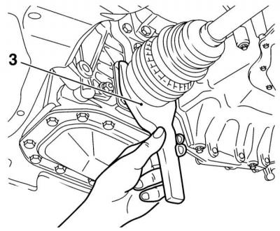
You can also use a hammer with a sliding striker screwed to the bar inserted under the inner CV joint.
Instead of a fork lever, you can use a conventional mount just as effectively.
15. Trying not to load the hinge, release the shaft trunnion from the differential and remove it from under the car. Seal the shaft mounting hole immediately to prevent dirt from entering the differential.
Lowering the vehicle to the ground with even one drive shaft removed can damage the wheel bearings! In case of emergency, tighten the bearings with a long bolt and nut and a pair of washers.
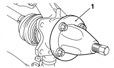
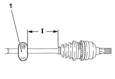
16. The right drive shaft on all models is equipped with a torsional vibration damper (1). In the event of a shaft replacement, the damper must be moved to a replacement assembly. measure the distance (I) from the outer CV joint to the damper installation site, - the required value is given in Specifications.
Installation
A new hub nut and a new inner circlip will be required.
1. Before installing the shaft, check the condition of the differential seal, if necessary, replace it (see chapter Manual transmission or automatic transmission).
2. Remove the retaining ring from the shaft stub and install a new one in its place.
3. Thoroughly clean the splines of the shaft and the hole in the hub. Lubricate the oil seal lips and the shaft studs with clean gear oil/ATF. Check the reliability of fixing the protective covers of the CV joints with your clamps.
4. Carefully, being careful not to damage the oil seal, thread the inner shaft trunnion into the transmission and engage it with the differential side gear splines. Push the shaft into the differential until the retaining ring snaps into place - tap with a heavy hammer with a soft head on the end of the outer hinge.
5. Insert the spline pin of the outer joint into engagement with the spokes of the hub.
6. Pull the lower suspension arm down with the lever and insert the ball pin shank into the clamp until it stops.
7. Insert clamp bolt (head first on the car) and tighten it to the required torque.
8. Connect the vertical link of the anti-roll bar to the suspension strut and tighten the fixing nut with the required force, - hold the hinge pin from turning with an open-end wrench by the flats.
9. Thread the flexible brake hose into the support bracket and secure the latter to the suspension strut by firmly tightening the mounting bolt.
10. Having tightened with the demanded effort a nut, fix a tip of steering draft in a rotary fist.
11. Put a washer on the drive shaft, screw on a new nut and tighten it until only by hand.
12. If equipped, install the crankcase protection. Install the wheel, lower the vehicle to the ground and tighten the wheel bolts to the correct torque.
13. Tighten the hub nut to the required torque in several steps (see Specifications). Secure the nut with a new cotter pin, tightening it if necessary to align the spline with the hole - do not forget to bend the antennae of the spline around the shaft pin and cut off the excess.
14. Install the wheel nut cap and wheel trim.
15. Fill the transmission with the required amount of oil / ATF of the required grade (see chapter Current service).
Visitor comments