
OpelBook.ru
Cars AvtoVAZ Cars Mitsubishi Cars BMW Cars Mercedes Cars Nissan Cars Toyota Cars Chevrolet
English Русский
Български
Беларускі
Український
Српски
Hrvatski
Română
Polski
Slovenský
Magyar
 |  Sitemap  |  Contacts  |    


Main Astra Corsa Insignia Kadett Omega Vectra Zafira Others Articles
Vectra A (1988-1995, petrol) Vectra A (1988-1995) Vectra B (1995-2002, petrol) Vectra B (1995-2002) Vectra C (2002-2008)
  • Main
  • Vectra
  • Vectra C
  • Transmission
  • Drive shafts
  • Removal and installation drive shafts

Removal and installation drive shafts (Opel Vectra C)

            0

Contents: Removal ⬇ Installation ⬇

Removal


Caution: When pulling the drive shaft journal out of the corresponding splined joint, the shaft must be pulled by the joint assembly - never by the shaft itself!


1. Engage neutral gear (manual transmission)/move the selector lever to the "N" position (AT).

2. Loosen the hub nut of the corresponding front wheel (see Chapter 10).

3. Loosen the nuts of the corresponding front wheel, jack up the front of the car and place it on supports. Remove the wheel.

Note: If the vehicle is equipped with directional tires, note the direction of rotation of the tires. If necessary, remove the crankcase guard (see Chapter 2).


4. Check the hydraulic support of the front suspension wishbone (see Chapter 10).

5. Loosen the tie rod end mounting nut and use a special puller to release the latter from the steering knuckle (see Chapter 10).

6. Unscrew the bolt (Togh) of the clamp securing the ball joint to the steering knuckle (see accompanying illustration)
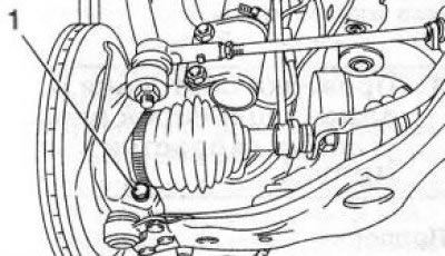
2.6 Bolt (1) of the clamp securing the ball joint to the steering knuckle (the illustration shows…

2.6 Bolt (1) of the clamp securing the ball joint to the steering knuckle (the illustration shows another Opel model)


Note that the bolt is facing forward on the vehicle. Press the wishbone down and disconnect it from the steering knuckle.

Note: The use of any tool for this purpose is not permitted.


7. Secure the drive shaft with wire or a support so that when removing it from the hub, it does not hang down on the inner CV joint.

8. Install the puller on the hub of the corresponding wheel (see accompanying illustration) and secure it with the wheel bolts. Using a puller, separate the drive shaft from the hub.
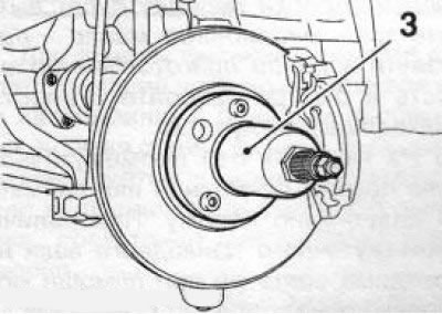
2.8 Puller (3) for removing the drive shaft from the wheel hub

2.8 Puller (3) for removing the drive shaft from the wheel hub


Caution: After removing the drive shaft, the wheel hub must not be loaded (use as a support), and the vehicle must not be moved - otherwise the wheel bearing may be damaged! If for any reason the vehicle needs to be moved, be sure to insert the drive shaft element into the hub and tighten the hub nut!


9. To remove the left drive shaft, use a pry bar to press the inner CV joint out of the splined connection (see accompanying illustration) and remove the shaft.
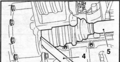
2.9 To separate from the gearbox, press the drive shaft (5) using a crowbar (4)

2.9 To separate from the gearbox, press the drive shaft (5) using a crowbar (4)


Attention: When removing the drive shaft from the gearbox housing, transmission oil will leak out - place a previously prepared container underneath and quickly close the hole with a suitable plug!


10. On models without an intermediate shaft, the right drive shaft is removed in the same way as the left one. If there is an intermediate drive shaft, it is necessary to use a crowbar to press the right drive shaft away from the intermediate shaft(see accompanying illustration).
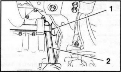
2.10 Removing the right drive shaft (1) from the splined connection with the intermediate shaft…

2.10 Removing the right drive shaft (1) from the splined connection with the intermediate shaft using a crowbar (2)


11. Carefully remove the drive shaft from the engine compartment.

Installation


Note: A new hub nut and new inner snap ring will be required.


12. Remove the retaining ring from the drive/intermediate shaft journal and install a new one in its place.

13. Thoroughly clean the shaft splines and the hole in the hub. Lubricate the sealing lips of the oil seal and the shaft splines with clean transmission oil/ATF. Check the reliability of the CV joint boot fixation with your clamps.

14. Carefully, being careful not to damage the seal, engage the inner journal of the drive shaft with the splines of the differential/intermediate shaft side gear - if necessary, use a mandrel sleeve to protect the seal (for example, Opel KM-6332). Push the shaft into the differential until the locking ring snaps into place, using a plastic hammer if necessary. To install the right drive shaft onto the intermediate shaft, use a hammer and a brass mandrel - the mandrel should be installed on the thickening of the end face of the joint being installed (see accompanying illustration)
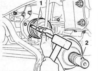


2.14 Installing the right drive shaft (2) using a hammer and brass mandrel (1)

2.14 Installing the right drive shaft (2) using a hammer and brass mandrel (1)


15. Engage the splined pin of the outer joint with the splines of the hub.

Caution: Be careful not to allow the drive shafts to hang on the dust boots for long periods of time!


16. Further installation is carried out in the reverse order of removal. Upon completion of the operation, check the transmission oil level and make the appropriate adjustments if necessary.


This article is available at russian, bulgarian, belarusian, ukrainian, serbian, croatian, romanian, polish, slovak, hungarian
Checking the article: Meshcheryakov Damir

Share information:

Previous articles
Opel Vectra C: Drive shafts
Next articles

General information about drive shafts
Drive shaft specifications
Removal and installation the intermediate shaft
Checking and replacing constant velocity joints (CV joints)
Replacing CV joint boots


See similar ones from other Opel car manuals:
▶ Seals (drive shafts) on the differential side Opel Astra F (1991-1998, petrol)
▶ General information about clutches and drive shafts Opel Corsa B (1993-2000)
▶ Replacing the secondary drive chain (drive chain of the… Opel Insignia A (2008-2017)
▶ Removal and installation front wheel drive shafts Opel Kadett E (1984-1995)
▶ Main gear and drive shafts Opel Omega A (1986-1993)
Link to this page in different formats

Visitor comments


No comments yet


How much will 36 + 19 =


Vectra C (2002-2008) 
  • General information
  • User manual
  • Vehicle device
  • Maintenance
  • Troubleshooting
  • Power unit
  • Engine repair
  • Cooling system
  • Power and control system
  • Engine electrics
  • Transmission
  • Clutch
  • Car gearbox
  • Drive shafts
  • Chassis
  • Car suspension
  • Steering
  • Brake system
  • Body
  • Exterior
  • Interior
  • Doors, locks and windows
  • Heating and ventilation
  • Electrical equipment
  • Equipment and devices
  • Headlights and lighting
  • Electrical circuits
Vectra B (1995-2002) 
  • General information
  • User manual
  • Weekly checks
  • Maintenance (gasoline)
  • Maintenance (diesel)
  • Troubleshooting
  • Power unit
  • SOHC gasoline engine
  • DOHC petrol engine
  • Diesel engine 1.7 liter
  • Diesel engine 2.0 liters
  • Engine repair
  • Cooling system
  • Fuel system (gasoline)
  • Fuel system (diesel)
  • Charging system
  • Launch system
  • Ignition and preheat
  • Transmission
  • Clutch
  • Mechanical gearbox
  • Automatic gearbox
  • Drive shafts
  • Chassis
  • Brake system
  • Wheel suspension
  • Steering
  • Body
  • Exterior
  • Interior
  • Doors and windows
  • Heating and ventilation
  • Electrical equipment
  • Equipment and devices
  • Electrical circuits
Vectra B (1995-2002, petrol) 
  • General information
  • Maintenance
  • Help with malfunctions
  • Power unit
  • Engine repair
  • Exhaust system
  • Cooling system
  • Fuel system
  • Multec injection system
  • Four point injection
  • Transmission
  • Clutch
  • Gearbox and drive
  • Chassis
  • Wheel suspension
  • Steering
  • Brake system
  • Wheels and tires
  • Body
  • Exterior
  • Interior
  • Electrical equipment
  • Fuses and electronics
  • Power devices
  • Ignition system
  • Lighting and signaling
  • Equipment and devices
  • Heating and ventilation
  • Electrical circuits
Vectra A (1988-1995) 
  • Power unit
  • Engine repair
  • Ignition system
  • Lubrication system
  • Cooling system
  • Injection system
  • Fuel system (carburetor)
  • Fuel system (diesel)
  • Exhaust system
  • Transmission
  • Clutch
  • Car gearbox
  • Chassis
  • Front suspension
  • Rear suspension
  • Steering
  • Brake system
  • Wheels and tires
  • Body
  • Exterior
  • Interior
  • Electrical equipment
  • Electrical circuits
Vectra A (1988-1995, petrol) 
  • General information
  • User manual
  • Maintenance
  • Power unit
  • SOHC engine
  • DOHC engine
  • Cooling and ventilation
  • Fuel system (carburetor)
  • Fuel system (injector)
  • Exhaust converter
  • Transmission
  • Clutch
  • Mechanical gearbox
  • Automatic gearbox
  • Drive shafts
  • Chassis
  • Brake system
  • Car suspension
  • Steering
  • Body
  • Body elements
  • Electrical equipment
  • Power devices
  • Equipment and devices
  • Electrical circuits
OpelBook.ru © 2017–2026 · Mobile version · · Sitemap: EN BG BY UA RS HR RO PL SK HU · Feedback · Site search
Astra F, petrol · Astra G, petrol · Astra G · Astra H · Astra J, petrol · Corsa B · Corsa C, petrol · Corsa C · Insignia A · Kadett D · Kadett E · Omega A · Omega B · Omega B2 · Vectra A, petrol · Vectra A · Vectra B, petrol · Vectra B · Vectra C · Zafira A, petrol · Frontera A, petrol · Frontera B · Ascona C · Vivaro A ·
We want your visit to be comfortable 🤝! We use cookies 🍪 to make that happen.