
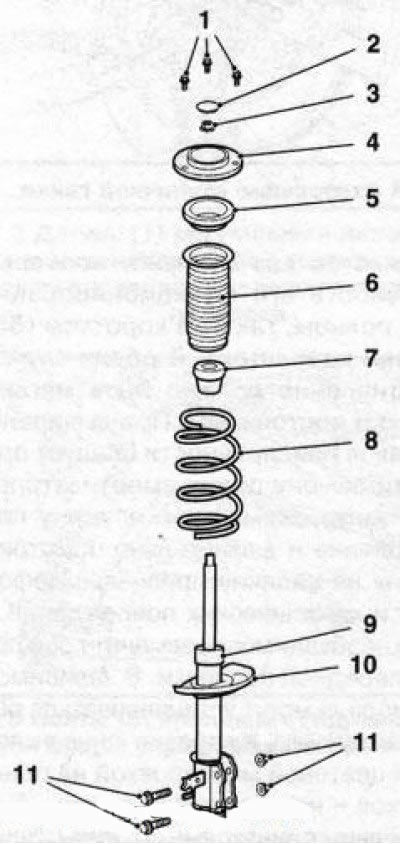
2.1 The design of the front shock absorber: 1. Top fixing bolts; 2. cap; 3. Support bearing fastening nut; 4. Top thrust washer; 5. Upper thrust bearing; 6. Anther; 7. Compression damper; 8. Helical spring; 9. Shock absorber; 10. Bottom thrust washer; 11. Bottom mounting bolts and nuts
2. Remove the corresponding wheel.
3. Release the brake pad wear sensor wiring harness and brake hose from the holders on the shock absorber strut (see resist. illustration), remove the mounting bolt and remove the ABS sensor holder from the strut.
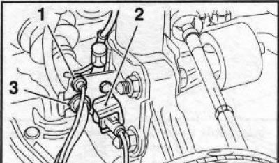
2.3 Mounting lines on the shock absorber strut: 1. Brake pad wear sensor wiring harness holder; 2. ABS sensor holder; 3. Brake hose holder; 5. Shock absorber
Note: In illustrations 2.3 and 2.4, the position of the bolts is shown incorrectly.
4. Loosen the top fixing nut (see resist. illustration) anti-roll bar struts, holding the strut mounting axis from turning with a second wrench. Remove the axle and disconnect the rack.
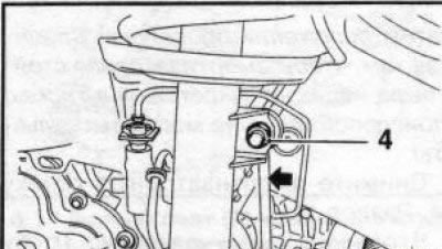
2.4 Top nut (4) anti-roll bar mounts
5. Place a hydraulic jack under the appropriate control arm.
6. Mark the position of the lower mounting bolts (see resist. illustration) on the steering knuckle, for which circle their heads with a marker.
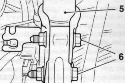
2.6 Bottom bolts (6) front shock absorber mounts
Attention: During installation, the bolts must be installed strictly in the same place - when the position of the bolts changes, the camber will change!
7. Release fixing nuts, take the bottom bolts of a shock-absorber rack. Lower the jack and separate the bottom of the shock absorber from the steering knuckle.
8. Open the hood. Remove the 3 top fixing screws (see resist. illustration) and remove the shock absorber strut from the arch of the front kotes.
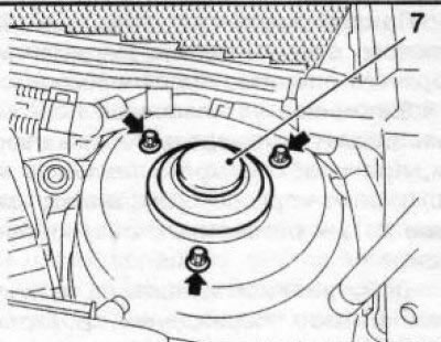
2.8 Top bolts (indicated by arrows) shock absorber mounts (7)
9. Installation is made in an order, the return to an order of removal. When installing, use only new self-locking bolts and nuts. Bolts/nuts of fastening of a shock-absorber rack are tightened in 3 steps (see specs), the lower bolts and the upper stabilizer strut mounting bolt must be inserted from the front.
The heads of the lower bolts must be aligned with the previously applied marks. At service stations, a special Hazet 6690 template is used to check the wheel alignment; for individual use, you can cut out the corresponding template from thick cardboard.
10. If the strut was removed outside the service workshop, have the camber checked by a workshop as soon as possible using special equipment.
Attention: The lower self-locking mounting bolts and nuts of the shock absorber strut must be replaced after each unscrewing! It is recommended that you always have a spare set of bolts and nuts in your vehicle.
Visitor comments