
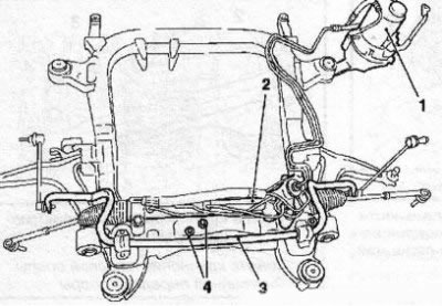
7.1a Front suspension subframe with installed equipment: 1. Power steering assembly; 2. Assembling the steering mechanism with rods; 3. Anti-roll bar; 4. Fastening the rear engine mount
To remove the subframe, you will need a hydraulic jack with sufficient travel and special tools KM-904 and KM-6312 with axles for centering the subframe during installation (see illustration 7.1b).
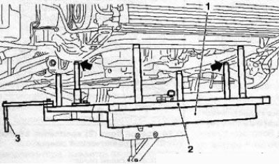
7.1b Special tools for removing/installing the subframe: 1. KM-904; 2. KM-6312; 3. Centering axes
2. Bring the front wheels of the car into a straight line, remove the key from the ignition and lock the steering wheel.
3. Using a wire, fasten the radiator of the cooling system on the front of the engine compartment on both sides and install and secure the special tool MKM-883-1 (see resist. illustration) with a set of rigging equipment for hanging the engine. Before use, carefully read the instruction manual for the kit.
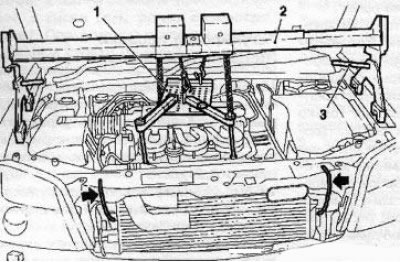
7.3 Hanging the engine using a set of special tools, the arrows indicate the wire fasteners of the radiator: 1.MKM-883-2; 2. MKM-883-1; 3.MKM-883-3
Note: Alternatively, any winch type hoist can be used.
4. Remove both front wheels.
5. Remove the front bumper cover (see chapter 11).
6. Remove the exhaust system (see chapter 4).
7. Turn out a bolt and disconnect an intermediate steering shaft from the steering mechanism.
8. Disconnect the front support and rear engine mount bracket from the subframe.
9. Disconnect the tie rod ends (see Section 15) and ball (outdoor) control arm supports from the steering knuckle.
Note: It is not necessary to detach the inner arm supports.
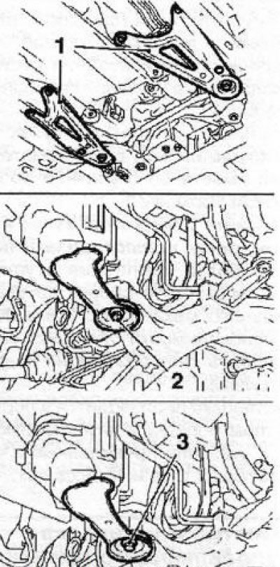
10. Loosen the fixing nut and disconnect the lower ends of the vertical struts of the anti-roll bar from the stabilizer (see resist. illustration).
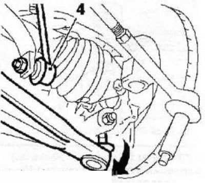
7.10 Bottom support (4) vertical stabilizer bar
11. Disconnect the power steering wiring connectors, release the wiring harnesses from the holders on the subframe and take them aside. On models equipped with xenon headlights, remove the headlight range sensor from the left control arm (see Section 6).
12. Support the subframe with a trolley jack, - in order to distribute the load, lay a special device on the head of the jack (see illustration 7.1b) in its absence, suitable wooden blocks can be placed.
13. Turn out on 3 bolts and remove triangular amplifiers of the back subframe holder (see resist. illustration). Remove the front subframe mounting bolts. Install the KM-6312-20 tool on the power steering assembly mounting bracket.
7.13 Subframe attachments: 1. Amplifiers of the rear holder; 2, 3. Front mounting bolts
14. Turn out 2 fixing bolts and disconnect assembly of the hydraulic booster from a body.
15. Using a jack, lower the subframe. If the subframe is to be replaced, reinstall all units and components (see illustration 7.1a) old subframe to a new one.
If necessary, replace the elements installed on the subframe.
16. Before lifting the subframe, move the centering axles of the KM-6312 tool (see illustration 7.1b) to the top position and secure with cotter pins. Installation is carried out in the reverse order to the dismantling of the components. Only new bolts must be used to mount the subframe. Tighten all fasteners to the required torque.
Visitor comments