
Suspension type
Front suspension - Independent, with MacPherson struts, gas-filled shock absorbers and anti-roll bar.
Rear suspension - Independent, multi-link type.
On Wagon/Signum models, a rear ride height adjustment system is fitted as an option.
General information
Note: Wagon and Signum suspensions are similar in design to those used on Sedan and Hatchback models. The difference between the models lies in the wheelbase, which is 13 cm longer on the Station Wagon/Signum models than on the Hatchback models.
Attention: When assembling the elements of the suspension and steering structure, it is imperative to comply with the requirements for the tightening force of threaded connections (see specs)!
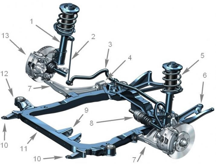
1.1 Front suspension design: 1. Shock absorber; 2. Vertical roll; 3. Anti-roll bar; 4. Hydraulic control arm support; 5. Helical spring shock absorber; 6. Left reinforcement of the rear subframe holder; 7. Suspension control arm 8 Drive shaft; 9. An arm of fastening of a forward support of the engine; 10. Lower radiator holders; 11. Subframe; 12. Damping rubber-metal supports of the subframe (4 things.); 13. Front brake caliper
1. The design of an independent front suspension with a subframe and lower control arms, MacPherson struts and an anti-roll bar is shown in Res. illustrations. The load-bearing element of the front suspension is a closed subframe, which is attached to the body at 4 points through damping supports. Additionally, 2 side supports are connected to the bottom of the body at the rear. The struts consist of telescopic shock absorbers and coil springs and are attached with their upper ends to reinforced supports on the mudguards of the front fenders, and with their lower ends to the steering knuckle assemblies by means of bolted connections. The hub with the wheel bearing is made in the form of a single compact unit, the non-adjustable bearings do not require maintenance. The hub assembly is installed in the steering knuckle. The lower parts of the steering knuckles are connected by means of ball bearings to the lower control arms of the suspension. The levers are attached to the subframe with inner ends, one of which (rear) a hydraulic support is installed to reduce noise and vibration when the vehicle is moving. The levers are designed to limit the lateral and longitudinal movement of the front wheels. In addition, due to some shift (bend) the central axis of the helical springs is compensated for transverse movements. An anti-roll bar is standard on all models. The stabilizer is mounted on a subframe and connected to the suspension struts by means of two vertical struts. It is designed to compensate for the lateral roll of the car when cornering. The front suspension does not require maintenance during operation.
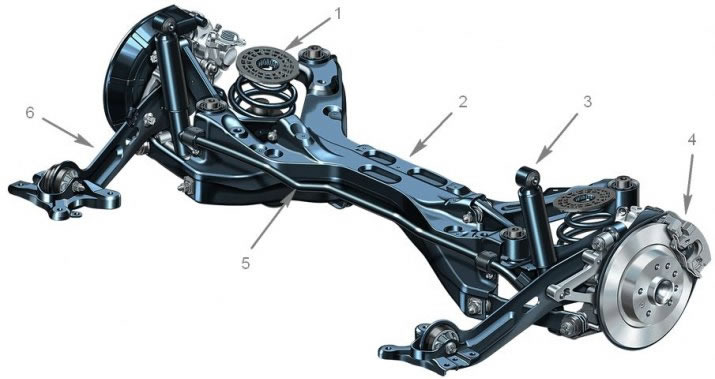
1.2 Rear suspension design: 1. Upper damping seat of the helical spring; 2. Rear suspension beam; 3. Shock absorber; 4. Rear brake caliper; 5. Anti-roll bar; 6. Trailing arm with damping rubber-metal support
2. The rear suspension consists of 2 trailing arms connected to each other by means of three transverse beams, and holders of the rear wheel hub assembly mounted on the arms (see resist. illustration). At the front ends of the levers, rubber-metal supports are equipped. Bolts are threaded through them, fixing the suspension arms in brackets bolted to the side members of the body. To reduce the weight of the rear suspension, part of the elements of the transverse beams is made of aluminum. The rear suspension is also equipped with an anti-roll bar to reduce vehicle roll when cornering and provide more reliable rear wheel traction. Suspension of the rear suspension is carried out by means of two coil springs and two shock absorbers. The upper ends of the shock absorbers are attached to the load-bearing elements of the bottom of the body. The springs are installed separately from the shock absorbers (due to this, the luggage compartment space is increased) and are fixed with two saddles, one of which is attached to the flange on the suspension, the other - to the bottom of the car. Some models may be equipped with a rear ride height adjustment system. As well as on the front suspension, the rear wheel hubs with bearings are made in the form of single units - the bearings do not require maintenance.
4. Often, during the process of replacing suspension components, one has to deal with fasteners that cannot be released. «sticking» fasteners due to the fact that they are constantly exposed to external influences, are in contact with water, dirt, soot and other substances that contribute to the development of corrosion. In order to facilitate the procedure for giving such «stuck» fasteners, it should be impregnated in advance with a copious amount of penetrating oil or a special agent for corroding rust. Scouring exposed threaded parts of fasteners with a stiff wire brush also helps loosen rusted nuts. In especially severe cases, for release «stuck» bolts / nuts, you can use a chisel / drift and a heavy hammer. Make sure that the chisel / drift does not break, try not to damage the thread with inaccurate blows. As a last resort, you can heat the stubborn fastener and the components surrounding it with a blowtorch or gas burner. This technology, due to its potential fire hazard and risk of burns, should only be used if all other methods have failed. To increase the torque when releasing fasteners, various kinds of extensions, gates and pipe nozzles are used on them. Sometimes a nut/bolt starts to give in after it has been pre-tightened slightly in a clockwise direction. All fasteners, the release of which required the use of extraordinary measures during assembly, must be replaced!
Note: After giving away, carefully check the condition of the fastener and, if necessary, replace it with elements of the same size.
5. Since the maintenance procedures for the suspension components are performed under the vehicle, care should be taken in advance to raise the vehicle and fix it in a raised position (prepare a reliable jack and props
Caution: Never carry out any work under the vehicle, which is secured in the raised position only with a jack.
6. Optimum driving performance and minimum tire wear are achieved with correct wheel alignment. In case of uneven tire wear, as well as unsatisfactory road holding, it is necessary to check the geometry of the suspension and wheel alignment. This will require a series of optical measurements that can only be made with special equipment.
Visitor comments