
Attention: When assembling the elements of the suspension and steering structure, it is imperative to comply with the requirements for the tightening force of threaded connections (see specs)!
Note: The Meriva models, unlike the Corsa C models, have a wider (by 20 mm) track by changing the design of the transverse levers. The rest of the suspension of both models are fundamentally similar.
1. The design of an independent front suspension with a subframe and lower control arms, MacPherson struts and an anti-roll bar is shown in Res. illustrations. The load-bearing element of the front suspension is a closed subframe, which is attached to the body at 4 points through damping supports. The subframe houses the mounting points for the wishbones, steering gear, radiator, and engine mounts. By means of damping supports, oscillations and vibrations of the power unit are compensated along the vertical axis, and by means of engine supports - in the longitudinal direction. The struts consist of telescopic shock absorbers and coil springs and are attached with their upper ends to reinforced supports on the mudguards of the front fenders, and with their lower ends to the steering knuckle assemblies by means of bolted connections. The hub and wheel bearing of the front wheel are installed in the steering knuckle, they do not require routine maintenance. The lower parts of the steering knuckles are connected to the lower transverse suspension arms by means of ball bearings. The levers are attached to the subframe with inner ends, one of which (front) a hydraulic support is installed to reduce noise and vibration when the vehicle is moving. The levers are designed to limit the lateral and longitudinal movement of the front wheels. An anti-roll bar is standard on all models. The stabilizer is mounted on a subframe and connected to the suspension struts by means of two vertical struts. It is designed to compensate for the side roll of the car body when cornering. On these models, both ends of the coil springs are tapered. Thanks to this shape, the transverse forces acting on the shock absorber rod are compensated without the usual angle of the springs in such cases. At the same time, the springs themselves occupy a smaller volume and have a smaller mass. The front suspension does not require maintenance during operation.
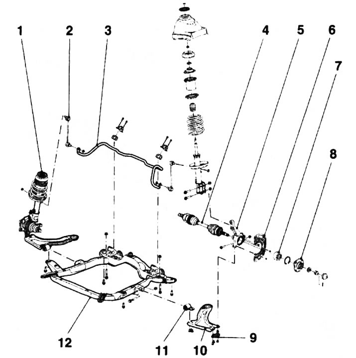
1.1. Front suspension design: 1. Shock absorber; 2. Vertical roll; 3. Anti-roll bar; 4. Drive shaft; 5. Knuckle; 6. Brake shield; 7. Wheel bearing; 8. Hub; 9. Ball joint; 10. Wishbone; 11. Hydraulic control arm support; 12. Subframe
2. The rear suspension consists of 2 trailing arms on which the hub assemblies are mounted. The levers are interconnected by means of a transverse beam. The design of the beam depends on the power of the engine and the carrying capacity of the vehicle. On models equipped with low power engines, a U-profile crossbeam is installed with a torsion bar inside (see illustration 1.2a). Models with more powerful traction and lifting characteristics are equipped with a tubular beam (see illustration 1.2b). At the front ends of the levers, rubber-metal supports are equipped. Bolts are threaded through them, fixing the suspension arms in brackets bolted to the side members of the body. On Meriva models, the rear suspension is equipped with an anti-roll bar to reduce vehicle roll when cornering and provide better rear wheel traction. Suspension of the rear suspension is carried out by means of two coil springs and two shock absorbers. The upper ends of the shock absorbers are attached to the load-bearing elements of the bottom of the body. The springs are installed separately from the shock absorbers and are fixed by two saddles, one of which is attached to the flange on the suspension, the other to the bottom of the car. Attached to the design, the suspension attachment elements do not take up space in the luggage compartment, thereby increasing the useful volume of the latter. The rear wheel hubs with bearings are made in the form of single non-separable units and do not require routine maintenance. On models equipped with drum brakes, wheel bearings are installed in the hub of the brake drum.
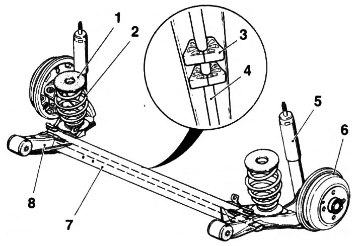
1.2a. Rear suspension design for Corsa C models (Z10XE engines (P) /Z12XE/Z17DT): 1. Upper damping seat; 2. Helical spring; 3. Torsion dampers; 4. Torsion; 5. Shock absorber; 6. Drum brake mechanism; 7. U-shaped cross beam; 8. Trailing arm with damping rubber-metal support
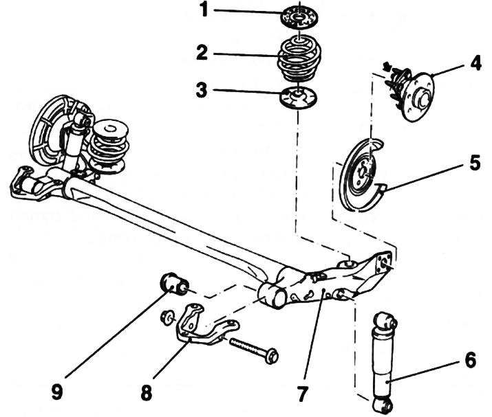
1.2b. The design of the rear suspension of Meriva models - the sensor is indicated by the arrow: 1. Upper damping seat; 2. Helical spring; 3. Lower damping saddle; 4. Hub assembly; 5. Brake shield; 6. Shock absorber; 7. Trailing arm; 8. Rear suspension bracket; 9. Rubber-metal bushing
3. The main elements of steering are the steering wheel with steering column, the steering gear with the rack and pinion and the tie rods (see resist. illustration). The column is connected to the mechanism by means of an intermediate shaft equipped with crosses. The upper section of the steering column is equipped with a lock that blocks the steering gear. The steering column transmits the control movement to the steering mechanism through gearing with the rack. The steering mechanism is mounted on the front suspension subframe. Tie rods are attached to the steering knuckle levers with tips. The steering mechanism must not have play and, accordingly, does not have adjustment indicators. When carrying out maintenance, it is only necessary to check the condition of the anthers and tie rod ends. If the anthers are damaged or play appears as a result of wear of the tips, it is necessary to replace the corresponding elements. The models described in this manual are equipped with electric power steering. The drive motor generates additional force on the steering column depending on the direction of the turn and ensures that the turn is carried out. Electric power steering does not require routine maintenance. The driver's airbag module is mounted in the hub of the steering wheel. Features of the operation of the additional security system (SRS) described in chapter «Controls and methods of operation».
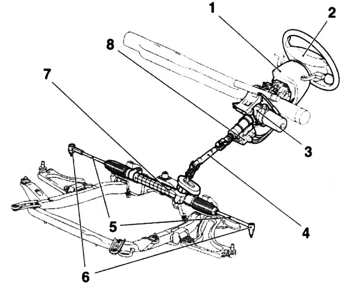
1.3. Steering gear design: 1. Facing the steering column; 2. Steering wheel; 3. Electric amplifier assembly (EPS) steering; 4. Intermediate steering shaft; 5. Tie rods; 6. Tie rod ends; 7. Steering gear; 8.EPS control module
4. Often, during the process of replacing suspension components, one has to deal with fasteners that cannot be released. «sticking» fasteners due to the fact that they are constantly exposed to external influences, are in contact with water, dirt, soot and other substances that contribute to the development of corrosion. In order to facilitate the procedure for giving such «stuck» fasteners, it should be impregnated in advance with a copious amount of penetrating oil or a special agent for corroding rust. Scouring exposed threaded parts of fasteners with a stiff wire brush also helps loosen rusted nuts. In especially severe cases, for release «stuck» bolts / nuts, you can use a chisel / drift and a heavy hammer. Make sure that the chisel / drift does not break, try not to damage the thread with inaccurate blows. As a last resort, you can heat the stubborn fastener and the components surrounding it with a blowtorch or gas burner. This technology, due to its potential fire and burn hazard, should only be used if all other methods have failed. To increase the torque when releasing fasteners, various kinds of extensions, gates and pipe nozzles are used on them. Sometimes a nut/bolt starts to give in after it has been pre-tightened slightly in a clockwise direction. All fasteners, the release of which required the use of extraordinary measures during assembly, must be replaced!
Note: After giving away, carefully check the condition of the fastener and, if necessary, replace it with elements of the same size.
Attention: Do not under any circumstances perform restoration repairs by straightening or welding deformed and damaged suspension and steering components - replace defective parts with new ones!
5. Since the maintenance procedures for the suspension components are performed under the vehicle, care should be taken in advance to raise the vehicle and fix it in a raised position (prepare a reliable jack and stands).
Attention: Never carry out any work under the vehicle, which is secured in a raised position only with a jack!
6. Optimum driving performance and minimum tire wear are achieved with correct wheel alignment. In the event of uneven tire wear, as well as unsatisfactory road holding, it is necessary to check the geometry of the suspension and wheel alignment. This will require a series of optical measurements that can only be made with special equipment.
Visitor comments