


General information
1. The geometry of the suspension and its rigidity determine the possibility of limiting the vertical movements of the body and reducing its angular oscillations around the transverse and longitudinal axes. The front wheels turn around inclined axes, whose position is determined by the design of the car's suspension.
2. Initially, the geometry of the chassis and suspension is set at the manufacturer. On modern cars, the initial settings practically do not change during operation and rarely require adjustment, however, when replacing worn or damaged suspension and steering components, they are subject to mandatory inspection.
3. The most important are the following kinematic settings of wheel assemblies in relation to steering and the transmission of forces between the tires and the road surface. It should be remembered that wheel alignment angles significantly affect the stability of the vehicle, the speed and nature of tire wear, and fuel consumption. The nominal values of the wheel alignment angles subject to inspection and adjustment for the vehicles considered in this Manual are given in Specifications at the beginning of the chapter.
4. Convergence (convergence) (see accompanying illustration) is called the angle between the lines formed when a horizontal plane cuts the following planes:
- Plane of symmetry of the car;
- Wheel disk plane.
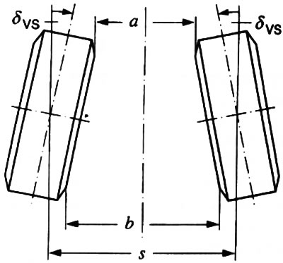
16.4. Front wheel toe-in:
δVS — Wheel alignment angle
a — Distance between the front edges of the wheels
b — Distance between the rear edges of the wheels
s — Track
b - a - Convergence
Note: Toe-in can also be defined as the difference in distances between the extreme front and rear edges of the wheel assemblies (see ibid).
Toe-in affects the straightness of the vehicle's movement and its controllability, and on front-wheel drive models it compensates for the resulting kinematic changes in the suspension geometry determined by the effect of traction force. With zero toe-in, the distance between the front edges of the wheels is equal to the distance between their rear edges. Normal toe-in usually does not exceed fractions of an inch (1 inch = 2.54 cm).
5. Collapse (see accompanying illustration) is the angle between the lines formed by the section of the following planes by a vertical plane perpendicular to the plane of symmetry of the car:
- Plane of symmetry of the car;
- Wheel disk plane.
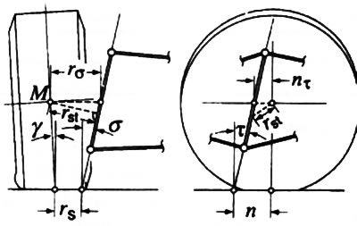
16.5. Wheel alignment angles:
M — Wheel Assembly Center
rst — Kinematic length of the journal
nτ — Longitudinal displacement of the wheel pivot axis
n — Positive stabilization arm
τ — Angle of longitudinal inclination of the wheel rotation axis
rσ — Lateral displacement of the wheel pivot axis
rs — Rolling shoulder
γ — Camber angle
S — Angle of transverse inclination of the wheel pivot axis
If the top of the wheel is tilted toward the axis of symmetry of the car, the camber is called negative, and vice versa. Correct camber adjustment determines the size and position of the contact patch of the treads with the road surface and allows for compensation of changes in the suspension geometry that occur during turns and when the car is moving on an uneven road surface.
6. The kinematic length of the journal is the shortest distance between the center of the steering wheel and its axis of rotation (see illustration 16.5). For all-wheel drive vehicles, this parameter characterizes the influence of traction forces and rolling resistance forces on the vehicle's controllability.
7. The stabilization shoulder is the distance between the point of contact of the wheel and the point of intersection of its rotation axis with the road surface in the side view (see illustration 16.5), which determines the magnitude of the stabilizing moment and affects the directional stability of the vehicle and the distribution of forces in the steering when making turns.
8. Coasting is the angle of longitudinal inclination of the wheel's rotation axis, i.e., the angle between the vertical and the line formed by the intersection of the plane of symmetry of the car with a plane perpendicular to it, drawn through the wheel's rotation axis (see illustration 16.5). Together with the axle tilt angle (see below), the coasting affects the change in wheel camber when measuring the steering wheel angle, and also affects the stabilizing moment.
9. The rolling shoulder is defined as the distance between the point of contact of the wheel with the road surface and the point of intersection of its turning axis with the road surface in the front view (see illustration 16.5). The shoulder is considered negative when the last of the above-mentioned points is between the center and the top of the wheel. The parameter affects the degree of impact of braking forces on the steering wheel and the magnitude of the stabilizing moment, and a negative running shoulder increases the latter.
10. The angle of transverse inclination of the wheel rotation axis is the angle of intersection of the vertical with the line formed by the intersection of the longitudinal plane drawn through the wheel rotation axis with the plane of the vehicle's cross section (see illustration 16.5). Along with the coasting (see above) and the magnitude of the longitudinal displacement of the pivot axis (see ibid) affects the sensitivity of the steering.
11. Another controlled parameter of suspension geometry is the full angle of rotation of the vehicle's steered wheels. The nominal values of this parameter are determined separately for the inner and outer wheels and must be the same for both directions of rotation.
12. General check of suspension geometry is performed on a special stand in a specialized workshop.
Conditions for checking wheel alignment angles
13. Checking the wheel alignment angles of a vehicle requires a specially equipped overpass. Before starting the check, make sure that the following conditions are met:
- The air pressure in the tires corresponds to the nominal;
- The front wheels are mounted in a straight line;
- The luggage compartment is not loaded, both front seats are loaded with 70 kg of cargo, the fuel tank is half full;
- The vehicle's suspension elements are forced down (you can also roll the car back and forth for 1 m);
- The steering gear is adjusted correctly;
- There is no play in the wheel bearings, tie rod ends or suspension ball joints;
- The tread depth of tires mounted on the wheels of the same axle is the same.
14. To check the toe-in and camber of the wheels in "home" conditions, you can use specially made templates made of thick cardboard, as mentioned in the relevant sections of this Chapter. However, at the first opportunity, check the geometry of the wheel installation in a special workshop.
Visitor comments