


2. Place the front wheels of the vehicle in a straight-ahead position, remove the key from the ignition and lock the steering wheel.
3. Remove the bolt and disconnect the intermediate steering shaft from the steering gear.
4. Install and secure the special device MKM-883-1 (see accompanying illustration) with a set of rigging equipment for hanging the engine. Before use, carefully read the operating instructions for the kit.
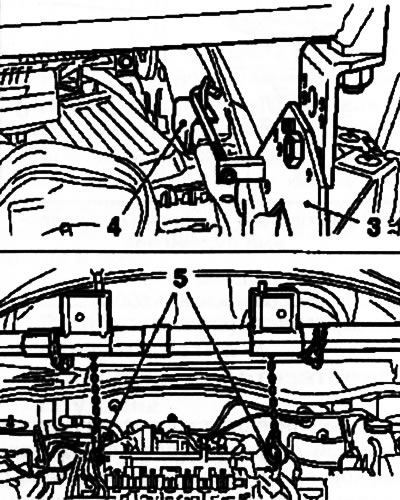
7.4. Hanging the engine using the MKM-883-1 special tool kit: 3. Cross beam support; 4. Fastening tie; 5. Rigging eyes
Note: Alternatively, any winch type lifting device can be used.
5. The lower radiator holders are secured to the subframe. To hold the radiator when the subframe is removed, secure it with wire on both sides to the front of the engine compartment.
6. Remove both front wheels.
7. Remove 3 expansion rivets (see accompanying illustration) fastening the front bumper cover to the subframe.
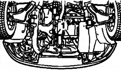
7.7. Rivets (1) for fastening the front bumper cover to the subframe
8. Remove the multi-rib belt cover and, on Corsa-Eco models, the engine sump guard (see Chapter 2).
9. Loosen the mounting nuts and disconnect the upper ends of the vertical stabilizer bar links from the stabilizer bar (see illustration 2.5).
10. Disconnect the tie rod ends (see Section 14) and ball joints of the transverse levers (see Section 6) from the steering knuckle.
11. Disconnect the electrical wiring from the pre-catalytic lambda probe and remove the exhaust system (see Chapter 4).
12. Install the right engine mount removal tool on the subframe (see Chapter 2).
Note: There are minor differences between fitting the kit on models with front and rear powertrain mounts and on models with only a rear mount - please read the kit instructions carefully.
13. Remove the retaining clip and detach the rear guide from the mounting bracket (see accompanying illustration). Unscrew the central bolts of the rear and front (on the corresponding models) power unit supports.
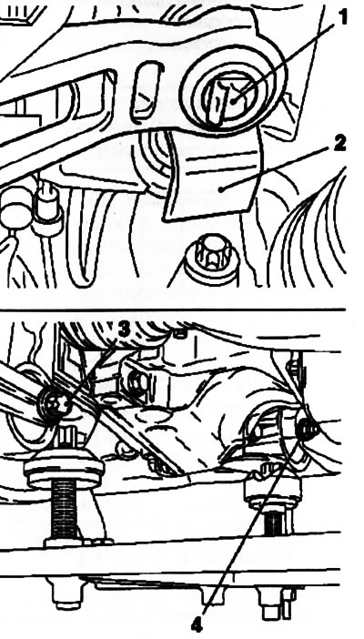
7.13. Central bolts of the rear (3) and front (4) engine mounts (power unit): 1. Locking bracket; 2. Rear guide
14. Install special devices KM-904 and KM-6168-A on the jack. Raise the devices on the jack and support the subframe as shown in the accompanying illustration.
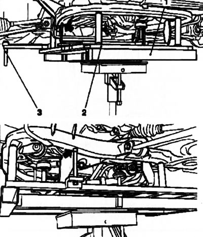
7.14. Special devices for removing/installing the subframe - arrows indicate holes for centering the device on the subframe: 1. KM-904; 2. KM-6168-A; 3. Installation centering axes
Note: When removing the subframe, the installation centering pins must be lowered to the lower position. They are designed to center the subframe relative to the car body only during installation.
15. Remove 4 mounting bolts (see accompanying illustration) and carefully, using a jack, lower the subframe.
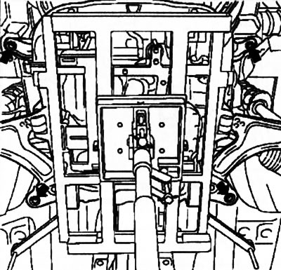
7.15. Bolts (indicated by arrows) subframe mounts
16. If the subframe needs to be replaced, reinstall all components (see accompanying illustration) old subframe to a new one. If necessary, replace the elements installed on the subframe.
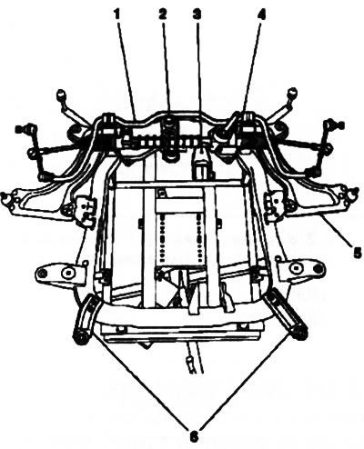
7.16. Front suspension subframe with installed equipment: 1. Anti-roll bar; 2. Rear guide mounting bracket; 3. Rear engine mount; 4. Assembling the steering mechanism with rods; 5. Wishbone; 6. Lower radiator holders
17. Before lifting the subframe, move the centering axes of the KM-6168-A device to the upper position and secure them with cotter pins. When lifting the subframe, they must fit into the corresponding holes in the body. Make sure that the radiator supports immediately fit into the holders on the subframe.
18. Further installation is carried out in the reverse order of dismantling the components. Only new bolts should be used to secure the subframe. Tighten all fasteners to the required force.
Visitor comments