


Note: Depending on the engine, the appearance, location and number of attachment points of the right support and its mounting bracket to the cylinder block may differ from that described below and shown in the accompanying illustrations. These design features of the engines have virtually no effect on the order in which this procedure is performed.
7. Due to the design features of the front suspension and the layout of the units in the engine compartment, for removal/replacement, the timing belt/chain (on some models and a multi-rib belt), and also for dismantling some units it is necessary to remove the right engine support. For this purpose, it is possible to dismantle the right support without removing the engine.
8. Before performing this operation, it is necessary to unload the right support. To do this, you will need a lifting device (hoist) with the appropriate devices for lifting the engine, or a universal set of devices from Opel for holding the engine on the front subframe of the car during removal/replacement of the support. In some cases, a jack can be used to hang the engine, placing a wooden block of suitable size between the jack head and the engine. All work involving the removal of engine supports is recommended to be performed at a service station.
9. At specialized Opel service stations, when removing the right support, a special set of devices KM-6169 is used to prevent the engine position from changing.
Note: For models produced since 2004, instead of the KM-6169-1 device, the KM-6394 device is used. The procedure for performing the operation is completely identical.
10. Disconnect the cable from the negative terminal of the battery (see Chapter 5) and remove the air cleaner (see Chapter 4).
11. Jack up and place the vehicle on stands or lift it. Remove the multi-rib belt cover or engine sump guard (see above).
12. Install the device Opel-KM-6169-2 (see accompanying illustration) on the gearbox and tighten the mounting bolts to 95 Nm.
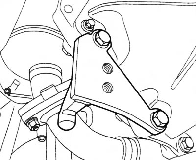
5.12. Installation of the Opel KM-6169-2 device
13. Install the device Opel-KM-6169 (see accompanying illustration) first on the left side of the subframe (I), then on the right (II). The guide pins of the device should enter the holes in the subframe. Tighten the mounting bolts.
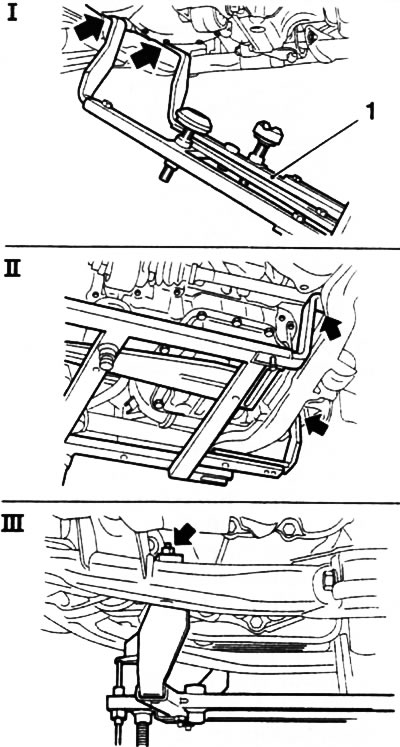
5.13. Installing the Opel-KM-6169 (1) device on the subframe
14. Install the 3 supports of the device and adjust their height (see accompanying illustration), first from the gearbox side (B) - the supports should fit tightly against the guide journals, then from the timing drive side (A) - the support should enter the hole in the engine block, if necessary, adjust the position of the support base on the device to align the support journal with the hole. Unscrew the supports upward until they rest against the support points of the power unit - the device should be tightly fixed on the subframe without play. Tighten the support fasteners.
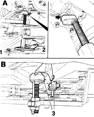
5.14. Installation and adjustment of the Opel-KM-6169 fixture supports: 1. Fastening nut of the support on the timing belt side; 2. Base of the support; 3. Gearbox side supports
15. Remove the lower bolt of the bracket securing the right support to the engine block (see illustration 5.15a). Lower the vehicle, unscrew the support mounting bolts to the side member and the upper bracket mounting bolts (see illustration 5.15b), - remove the engine support together with the bracket.
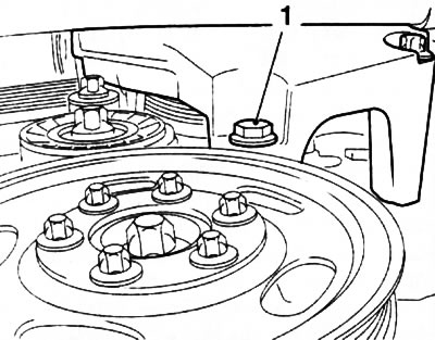
5.15a. Lower bolt (1) for fastening the right engine support bracket |
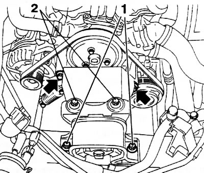
5.15b. Right engine support - the arrows show the upper bolts securing the right engine support bracket to the cylinder block |
16. If necessary, the engine support can be dismantled without removing the bracket. In this case, it is necessary to unscrew the 2 bolts securing the right support to the bracket (see illustration 5.15b).
17. When installing the support, first install the lower bracket mounting bolt and tighten it by hand. Tighten to the required torque (see Specifications) support mounting bolts to the side member, then the upper bracket mounting bolts and finally the lower bolt. If the bracket has not been removed, first tighten the support mounting bolts to the side member and then to the bracket. Dismantling the device is done in the reverse order.
Visitor comments