
OpelBook.ru
Cars AvtoVAZ Cars Mitsubishi Cars BMW Cars Mercedes Cars Nissan Cars Toyota Cars Chevrolet
English Русский
Български
Беларускі
Український
Српски
Hrvatski
Română
Polski
Slovenský
Magyar
 |  Sitemap  |  Contacts  |    


Main Astra Corsa Insignia Kadett Omega Vectra Zafira Others Articles
Corsa B (1993-2000) Corsa C (2000-2006, petrol) Corsa C (2000-2006)
  • Main
  • Corsa
  • Corsa C
  • Power unit
  • Engine repair
  • Engine condition diagnostics using a vacuum gauge

Engine condition diagnostics using a vacuum gauge (Opel Corsa C)

            0

1. Using a vacuum gauge at a relatively low cost allows you to obtain fairly comprehensive information about the internal condition of the engine. Based on the results of the measurements, you can get an idea of the degree of wear of the piston rings and cylinder mirrors, identify signs of failure of the cylinder head gaskets and intake manifold, violations of carburetor adjustments and the patency of the exhaust system, jamming or burnout of valves, sagging valve springs, failure to set the ignition timing or valve timing, failures of the ignition system, etc., etc.

2. The results of vacuum gauge readings must be analyzed in conjunction with the data obtained during other diagnostic tests, otherwise they can easily be misinterpreted and lead to erroneous conclusions.

3. When reading the vacuum gauge indicator, pay attention not only to the absolute value of the pointer's deflection, but also to its speed of movement. Most imported gauges show the vacuum depth in inches of mercury. It should be taken into account that all regulatory requirements are given for the case of testing at zero altitude above sea level. An increase in relief for every 300 m after the 600 m mark leads to an underestimation of the instrument's readings by approximately 25 mm Hg.

4. Connect the vacuum gauge directly to the intake manifold - not to the throttle body. Make sure that all hoses remain connected during the test, otherwise the reading will not be reliable.

5. Before taking measurements, warm up the engine to normal operating temperature. Chock the wheels and apply the parking brake. Shift the transmission to position "P", start the engine and let it run at normal idle speed.


Warning: When performing any work in the engine compartment with the engine running, be careful and follow safety precautions! Also avoid taking a position directly in front of the car!


6. Read the vacuum gauge readings. On average, the vacuum depth in the intake manifold of a serviceable engine should be fairly stable (without jerking the arrows) and be about 430 + 560 mm Hg. The following paragraphs provide a diagram for interpreting the readings taken (see accompanying illustration).
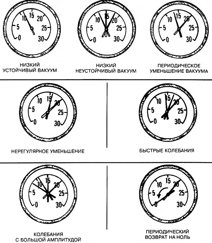
4.6. Examples of possible vacuum gauge readings

4.6. Examples of possible vacuum gauge readings


7. Consistently low readings may indicate leaks through the gasket between the intake manifold and the cylinder head, or between the manifold and the throttle body. It is also possible that the vacuum hose is leaking, or that the ignition timing is incorrect (towards lagging behind), or faulty valve timing. Check the ignition timing using a stroboscope, then eliminate all other possible causes one by one by performing the checks listed in this Chapter. Only then should you remove the timing belt cover to check that the timing marks are aligned correctly.

8. If the measurement result is 80+200 mm Hg below the norm and there are fluctuations, the cause of such a deviation may be a leak in the intake manifold gasket in the intake port area, or a malfunction of the fuel injection injector.


The article was published on the website (opelbook.ru)

9. Regular deviation of readings downwards from a stable value by 50+100 mm Hg with a high degree of probability indicates valve leaks. Check the compression pressure in the cylinders or conduct a leak test.

10. Irregular deviations and resets of readings may be due to valve sticking or misfiring. Measure compression pressure, conduct a leak test, check the condition of the spark plugs.

11. Frequent vibration of the gauge needle with an oscillation amplitude of 100 mm Hg at idle engine speed, accompanied by smoke emission from the exhaust pipe, indicates wear of the valve guide bushings. Conduct a leak test (see previous Section). If the needle starts to vibrate when the engine speed increases, check the intake manifold gasket and cylinder head for signs of leaks. Assess the degree of valve spring sag, check the valves for signs of burnout, and try to detect misfires.

12. Minor fluctuations within the range of 25 to 50 mm Hg may be considered as evidence of malfunction of the ignition system. Check the correctness of all normal settings, if necessary, resort to testing using an ignition parameter analyzer.

13. If the meter readings deviate widely, check the compression pressure or perform a leak test to identify a defective cylinder or a leaky cylinder head gasket.

14. If the meter needle slowly "walks" over a wide range of the scale, check the crankcase ventilation (PCV) system for patency and the idle mixture composition, and also make sure there are no leaks through the carburetor/throttle body gaskets and intake manifold.

15. Estimate the rate of recovery of the vacuum gauge readings when closing the throttle valve after its full rapid opening. The reading should first drop almost to zero, then rise above the value characteristic of normal idle speed by approximately 130 mm Hg and return to the idle speed reading again. If the vacuum depth is restored slowly and does not form a peak surge when the throttle valve is abruptly closed, you should check whether the piston rings are worn. If the readings are returned for a long time, check the patency of the exhaust system (often the muffler or catalytic converter is blocked) - the easiest way is to simply disconnect the suspect section of the exhaust system and repeat the test.


This article is available at russian, bulgarian, belarusian, ukrainian, serbian, croatian, romanian, polish, slovak, hungarian
Checking the article: Kornev Georgy

Share information:

Previous articles
Opel Corsa C: Engine repair
Next articles

Checking the compression pressure in the cylinders
Engine cover
List of works performed without removing the engine from the car
General information about engines
Specifications for engine repair
Removal and installation the multi-rib belt cover and engine crankcase protection
Removal the right engine mount
Removal and installation the crankshaft pulley
Removal and installation camshaft sprockets/wheels
Bringing the piston of the first cylinder to the top dead center (TDC) position
Removal and installation the accessory drive belt


See similar ones from other Opel car manuals:
▶ Engine condition diagnostics using a vacuum gauge Opel Astra H (2004-2009)
▶ Engine condition diagnostics using a vacuum gauge Opel Vectra C (2002-2008)
▶ Engine diagnostics using a vacuum gauge Opel Omega B (1993-1999)
▶ Engine management system — technical condition check and… Opel Zafira A (1999-2005, petrol)
▶ Determining engine faults by the condition of spark plugs Opel Insignia A (2008-2017)
Link to this page in different formats

Visitor comments


No comments yet


How much will 20 + 37 =


Corsa C (2000-2006) 
  • General information
  • Introduction to guide
  • Troubleshooting
  • Vehicle device
  • User manual
  • Maintenance
  • Power unit
  • Engine repair
  • Cooling system
  • Power and exhaust system
  • Control system
  • Engine electrical equipment
  • Transmission
  • Clutch
  • Mechanical gearbox
  • Automatic gearbox
  • Drive shafts
  • Chassis
  • Brake system
  • Wheel suspension
  • Steering
  • Body
  • Exterior
  • Interior
  • Doors and windows
  • Heating and air conditioning
  • Electrical equipment
  • Equipment and devices
  • Lamps and lighting
  • Electrical circuits
Corsa C (2000-2006, petrol) 
  • User manual
  • Car access
  • Governing bodies
  • Seat control
  • Heating and air conditioning
  • Driving and maintenance
  • Engines 1.0 and 1.2 l
  • Engine repair
  • Cooling and lubrication system
  • Injection system
  • Engines 1.4, 1.6 and 1.8 l
  • Engine repair
  • Cooling and lubrication system
  • Injection system
  • Transmission
  • Clutch
  • Mechanical gearbox
  • Automatic gearbox
  • Drive shafts
  • Chassis
  • Wheels and tires
  • Wheel suspension
  • Steering
  • Brake system
  • Body
  • Exterior
  • Doors and windows
  • Electrical equipment
  • Equipment and devices
  • Lighting system
  • Electrical circuits
Corsa B (1993-2000) 
  • General information
  • Introduction to guide
  • User manual
  • Maintenance
  • Power unit
  • SOHC gasoline engines
  • DOHC gasoline engines
  • Diesel engines
  • Engine repair
  • Cooling system
  • Supply system
  • Injection system (gasoline)
  • Injection system (diesel)
  • Exhaust systems
  • Control system (gasoline)
  • Preheat system (diesel)
  • Charge and launch system
  • Transmission
  • Mechanical gearbox
  • Automatic gearbox
  • Clutch and drive shafts
  • Chassis
  • Brake system
  • Front suspension
  • Rear suspension
  • Steering
  • Body
  • Ventilation and heating
  • Exterior
  • Interior
  • Doors and windows
  • Electrical equipment
  • Equipment and devices
  • Lamps and lighting
  • Electrical circuits
OpelBook.ru © 2017–2026 · Mobile version · · Sitemap: EN BG BY UA RS HR RO PL SK HU · Feedback · Site search
Astra F, petrol · Astra G, petrol · Astra G · Astra H · Astra J, petrol · Corsa B · Corsa C, petrol · Corsa C · Insignia A · Kadett D · Kadett E · Omega A · Omega B · Omega B2 · Vectra A, petrol · Vectra A · Vectra B, petrol · Vectra B · Vectra C · Zafira A, petrol · Frontera A, petrol · Frontera B · Ascona C · Vivaro A ·
We want your visit to be comfortable 🤝! We use cookies 🍪 to make that happen.