
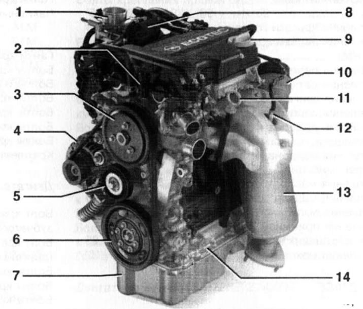
1.1a Petrol 3-cylinder engine 1.0 l (44 kW/60 hp): 1. Intake air duct; 2. Coolant temperature sensor; 3. Water pump drive pulley; 4. Generator; 5. Multirib belt tensioner; 6. Crankshaft pulley; 7. Engine oil pan; 8. Throttle control unit; 9. Oil filler cap; 10. Oil filter; 11. Engine oil level meter; 12. Pre-catalytic lambda probe; 13. Catalytic converter; 14. Bottom (aluminum) part of the cylinder block
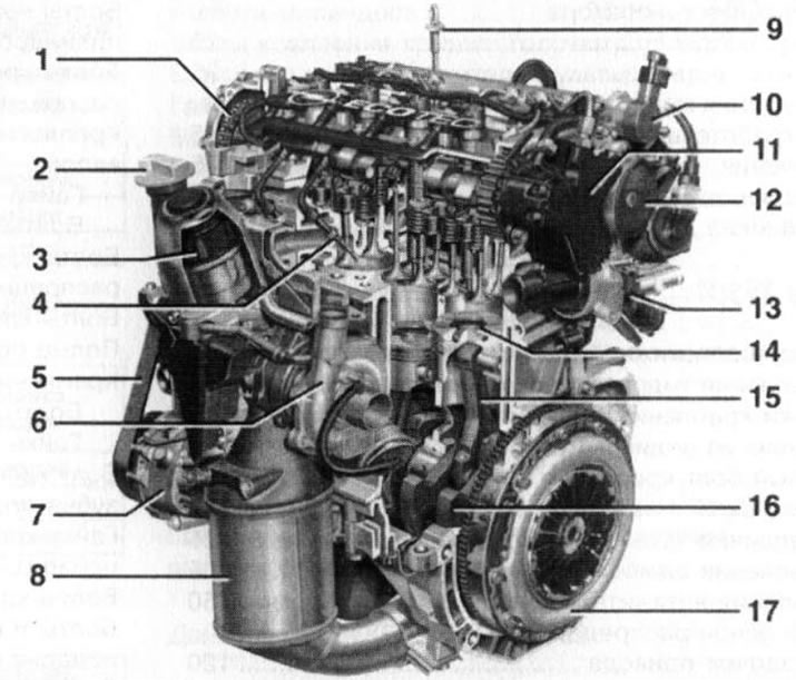
1.1b. Diesel 4-cylinder engine 1.3 l (51 kW/70 hp): 1. Timing chain; 2. Oil filler cap; 3. Oil filter; 4. Glow plug; 5. Multirib accessory drive belt; 6. Turbocharger; 7. Compressor of the A/C system; 8. Catalytic converter; 9. Engine oil level gauge; 10. Pressure regulator of the fuel supply system; 11. injection pump; 12. Vacuum pump; 13. Thermostat housing; 14. Piston; 15. Connecting rod; 16. Crankshaft; 17. Clutch basket
2. Models covered in this manual are equipped with 3-cylinder (Z1 OXE (R)) and 4-cylinder in-line engines. Almost all engines are equipped with two overhead camshafts (DOHC) and four valves per cylinder (2 intake and 2 exhaust). The only exception is the Z16SE 4-cylinder petrol engine, which has 2 valves per cylinder and one camshaft (SOHC).
3. The engine is installed transversely in the front of the car and fastened with rubber-metal supports. Due to the damping properties of the bearings, vibrations and vibrations of the power unit are damped and not transmitted to the body, which makes it possible to comfortably drive a car at low engine speeds and, accordingly, reduce fuel consumption. Engine cooling system - liquid type with forced cooling, engine lubrication system - closed type with a wet sump. The drive is carried out on the front wheels by means of a transmission assembly fixed to the left of the engine.
4. The cylinder block consists of two parts: the upper part is made of gray cast iron, and the lower part is made of aluminum alloy. Both parts are connected to each other by bolted connections. The lower part of the crankcase with integrated bearings supports the crankshaft. The cast cylinder head is made of aluminum alloy and has a threaded connection with the cylinder block. Aluminum has a higher thermal conductivity and a lower specific gravity than cast iron. Steel seats and valve guides are pressed into the head. Due to the presence of hydraulic compensators in most engines (except diesel with a working volume of 1.7 l) valve clearance is maintained automatically, eliminating the need for adjustment during engine maintenance.
5. A schematic diagram of the engine lubrication system is shown in Ref. illustrations. The lubrication system is powered by an oil pump driven by the crankshaft trunnion.
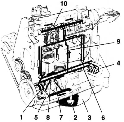
1.5. Schematic diagram of the engine lubrication system: 1. Oil pump; 2. Oil intake; 3. Pallet boat; 4. Full flow oil filter; 5. Pressure reducing valve; 6. Main oil line; 7. The main neck of the crankshaft; 8. Connecting rod neck of the crankshaft; 9. Vertical oil flow; 10. Camshaft journal
Note: On some engine models, the pump may be driven by a toothed belt.
Oil is drawn through a strainer-equipped oil pick-up from the engine sump and filtered by a full-flow replacement oil filter. The oil pump is equipped with a pressure reducing valve. When a certain pressure in the lubrication system is exceeded, the valve opens and excess oil drains into the boat sump. The oil moves along the oil flows provided in the block casting. From the oil filter, the main oil flow under pressure is supplied to the main oil line and further to the crankshaft bearings through special drillings in the shaft body, as well as to the piston bottoms and cylinder sleeve walls. At the same time, oil enters the cylinder heads through vertical channels to lubricate the camshaft bearings. When the full-flow oil filter is clogged, the bypass valve opens and oil is supplied to the main oil line bypassing the filter (unfiltered). Lubrication of the camshaft cams and valve components, as well as other internal engine components, is carried out by the splash method.
6. Opel continues to improve engine design. This manual discusses in more detail the modifications of engines of an earlier (up to 2004 inclusive) release. On cars of later years of production, already modified engines can be installed.
7. For Corsa C models, the base is the Z10XE 3-cylinder petrol engine. On this engine, the camshafts are driven by a chain and do not require constant maintenance. Since 2004, cars have been equipped with a modified Z10XEP engine with a Twinport system, a larger (by increasing the diameter of the cylinders) displacement and high compression ratio. At the request of the car owner, more powerful Z12XE / Z14XEP engines can be installed on Corsa C models. By design, they repeat the Z10XE engine, but have 4 cylinders.
8. Corsa Combo and Meriva models are equipped with Z14XE/Z16XE/Z18XE 16-valve petrol engines or Z16SE 8-valve engine. The camshafts of these engines are driven by a toothed belt. The impact on the angled intake/exhaust valves from the camshafts is transmitted via hydraulic tappets (compensators), and on the Z16SE engine, vertically mounted valves are driven through rocker arms.
9. Possibility of installation on cars of diesel engines is provided. The Z13DT engine is based on a 1.0L petrol engine and is also equipped with chain driven camshafts. On diesel engines with a displacement of 1.7 liters, the intake camshaft is driven by a toothed belt, and then to the exhaust camshaft through a spur gear.
10. To check the technical condition of the engine, to carry out work on diagnosing systems and mechanisms of the engine, its maintenance and repair, a fairly large range of special devices and instruments is required, and a certain experience in working with such a tool is also required, therefore the compilers of this Guide strongly recommend that you contact for carrying out Maintenance and repair at specialized service stations.
11. The format of this publication does not allow to fully describe all the disassembly/assembly operations of engines installed on the models described in this Manual. The following sections describe the procedure for performing only the basic work that is most often performed during maintenance and current repairs without removing the engine. Some operations are quite simple or are constantly repeated during the execution of work - in some cases, their description is omitted.
Note: Due to the constant modification of the vehicle structure and engines, some deviations from the procedures described below are possible. In this case, elementary ingenuity is required to dismantle / install parts or assemblies - carefully inspect them and determine which additional elements must first be disconnected or what prevents their dismantling. It is unlikely that the new options will be fundamentally different from those described below.
Visitor comments