
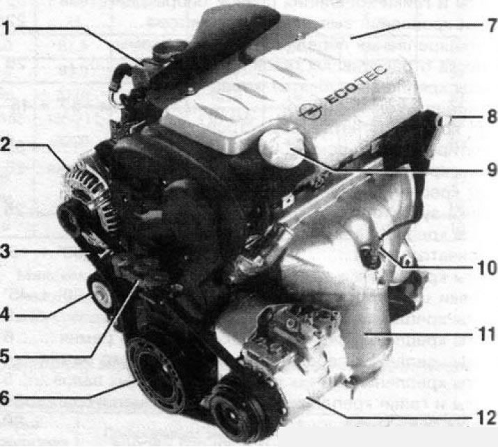
1.1a Petrol engine 1.8 l (90 kW/122 hp): 1. Throttle control unit; 2. Generator; 3. Multirib accessory drive belt; 4. Tension roller; 5. Bracket for fastening the right engine mount to the crankshaft pulley; 7. Engine cover; 8. Engine oil level meter; 9. Oil filler cap; 10. Dokatapitichesky lambda probe; 11. Protection of the exhaust manifold; 12. A/C system compressor
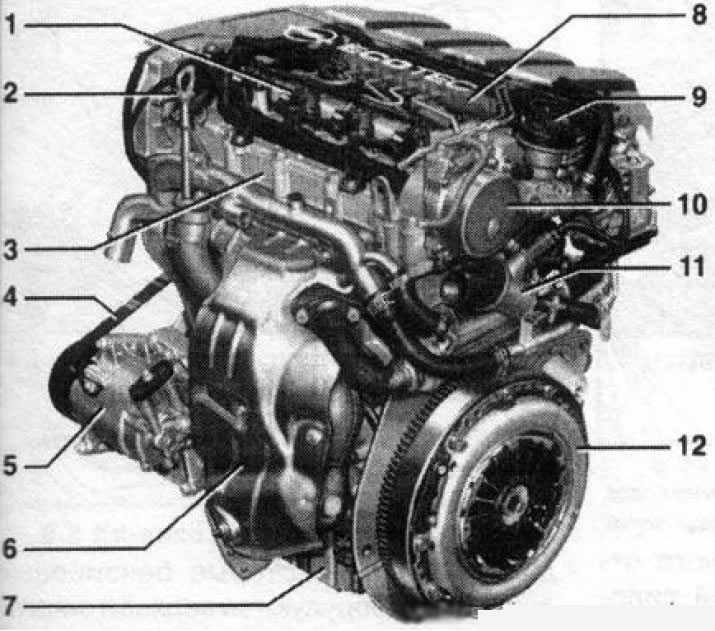
1.1b Diesel engine 1.9 l (110 kW/150 hp): 1. Nozzle; 2. Engine oil level gauge; 3. Cylinder head; 4. Multirib accessory drive belt; 5. Compressor of the A/C system; 6. Protection of the exhaust manifold; 7. Oil pan; 8. Fuel distribution line (Common Rail); 9. Oil filler cap; 10. Vacuum pump; 11. Thermostat housing; 12. Clutch basket
2. The models covered in this manual are designed for 4-cylinder in-line, 6-valve engines equipped with two overhead camshafts (DOHC) - Z16XE, Z18XE, Z22SE, Z22YH and Z19DTH, or single SO HC camshaft) - Y20DTH and Y22DTR). The only exception is the Z19DT diesel engine, which has 2 valves per cylinder (one camshaft). In addition, 6-cylinder 24-valve engines with a volume of 3.0 liters can be installed on cars (diesel) and 3.2 l (petrol) with a V-shaped arrangement of cylinders and four camshafts. The engine is mounted on rubber-metal supports transversely in the front of the car and has water cooling, the engine lubrication system is of a closed type with a wet sump. The drive is carried out on the front wheels by means of a transmission assembly fixed to the left of the engine.
3. The cast cylinder head is made of aluminum alloy and has a threaded connection with the cylinder block. Aluminum has a higher thermal conductivity and a lower specific gravity than cast iron. Steel seats and valve guides are pressed into the head. Due to the presence of a hydraulic compensator in most engines (except Z19DT and Y30DT) valve clearance is maintained automatically, eliminating the need for adjustment during engine maintenance.
4. A schematic diagram of the engine lubrication system is shown in resist. illustrations. The lubrication system is powered by an oil pump driven by the crankshaft trunnion. On some engine models, the pump can be driven by a toothed belt or chain. Oil is drawn through a strainer-equipped oil pick-up from the engine sump and filtered by a full-flow replacement oil filter. The oil pump is equipped with a pressure reducing valve. When a certain pressure in the lubrication system is exceeded, the valve opens and excess oil drains into the boat sump. The oil moves along the oil flows provided in the block casting. From the oil filter, the main oil flow under pressure is supplied to the main oil line and further to the crankshaft bearings through special drillings in the shaft body, as well as to the piston bottoms and cylinder sleeve walls. At the same time, oil enters the cylinder heads through vertical channels to lubricate the camshaft bearings. When the full-flow oil filter is clogged, the bypass valve opens and oil is supplied to the main oil line bypassing the filter (unfiltered). Lubrication of the camshaft cams and valve components, as well as other internal engine components, is carried out by the splash method.
Oil filter type:
- Z20NET/Z22SE/Z22YH/Z19DT/ Y20DTH/Y22DTR/Y30DT engines - with replaceable filter element
- Engines Z16XE, Z18XE (R) - non-separable, completely replaceable
- Permissible oil consumption per 1000 km of run, l - no more than 0.6
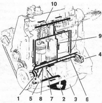
1.4 Schematic diagram of the engine lubrication system: 1. Oil pump; 2. Oil intake; 3. Pallet boat; 4. Full flow oil filter; 5. Pressure reducing valve; 6. Main oil line; 7. The main neck of the crankshaft; 8. Connecting rod neck of the crankshaft; 9. Vertical oil flow; 10. Camshaft journal
5. Opel continues to improve engine design. Due to the limited space and stinginess of information sources, only modifications of engines of an earlier (up to 2004 inclusive) release. At the time of the publication of the Manual, gasoline models equipped with a new 6-cylinder engine with a volume of 2.8 liters began to enter the Russian market, but Opel dealers do not yet have detailed information on its repair.
6. To check the technical condition of the engine, carry out work on diagnosing systems and mechanisms of the engine, its maintenance and repair, a fairly large range of special devices and devices with a set of adapters is required, and a certain experience in working with such a tool is also required, therefore the compilers of this Guide strongly recommend contact for maintenance and repair at specialized service stations of official representatives of Opel. In addition, the format of this publication does not allow a full description of all disassembly / assembly operations of engines installed on the models described in this manual. Therefore, the following sections provide a list and procedure for performing only the main, most frequently performed during maintenance and current repairs, operations. Some operations are quite simple and are constantly repeated during the execution of work - in some cases, their description is omitted.
Note: Due to the constant modification of the vehicle structure, incl. and engines, some deviations from the procedures described below are possible. In this case, elementary ingenuity is required to dismantle / install parts or assemblies - carefully inspect them and determine which additional elements must first be disconnected or what prevents their dismantling. It is unlikely that the new options will be fundamentally different from those described.
The list of repair work performed without removing the engine from the car (Maintenance and current repairs)
7. The following repairs listed below can be carried out without removing the engine from the vehicle:
- a) Compression check;
- b) Removal and installation of the cover of the gas distribution mechanism;
- c) Removal and installation of the timing cover;
- d) Removal and installation of timing drive components (belt/chain, cogwheels/sprockets);
- e) Removal and installation of camshafts and pushers;
- f) Valve clearance adjustment (diesel engines Z19DT and Y30DT);
- g) Removal and installation of the cylinder head;
- h) Removal and installation of the oil pan;
- i) Removal and installation of the oil pump;
- j) Removal and installation of the oil cooler (with appropriate equipment);
- k) Replacement of crankshaft and camshaft seals;
- l) Checking the condition and replacing the suspension mounts of the power unit;
- m) Removal, condition check and installation of a flywheel/drive disk.
8. Before starting work, thoroughly clean the engine compartment and external surfaces of the power unit using one of a wide range of special solvents. This treatment will prevent dirt from getting inside the engine.
9. If necessary, determined by the nature of the work to be done, you can remove the hood in order to provide freedom of access to the components to be serviced, - in order to avoid accidental damage to the paintwork, cover the car fenders with special covers, or simply with old blankets.
Visitor comments