
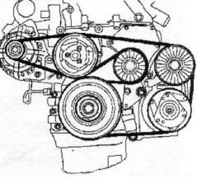
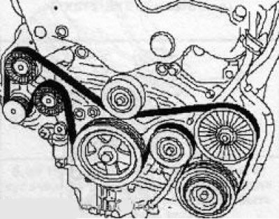
2. The multi-ribbed belt is designed to drive auxiliary units such as generator, water pump and air conditioner pump assembly. Depending on the engine model and configuration, the number of drive units may be different, respectively, the length of the belts will be different - be careful when buying a new belt for your car. Before removing the belt, it is recommended to draw a diagram of its tension.
3. On the models discussed in this manual, the multirib belt is removed from below - you must first hang the car on a lift.
4. On petrol models, remove the multirib belt cover; on diesel models, the engine crankcase protection must be removed.
5. If the belt is to be reused, make a mark with a marker before removing it from the pulleys (in the form of an arrow) to determine the direction of rotation of the multi-ribbed belt during subsequent installation.
Note: The belt rotates clockwise when looking at the engine from the belt drive side. If a previously used belt is installed without observing the direction of rotation, it will be subject to increased wear and will quickly fail.
Engines Z16XE/Z18XE
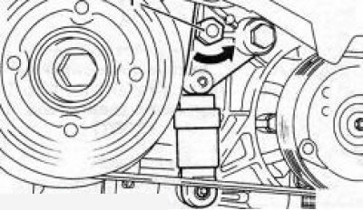
6. To loosen the multi-rib belt, use the central bolt of the tension roller (see illustration), for which using a conventional wrench (15 mm) - press it in the direction of the arrow and fix it with the locking rod. Then remove the belt.
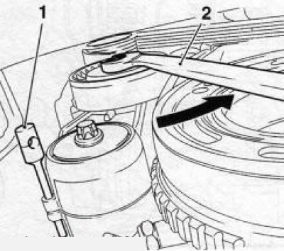
7.6 Depressing the tension roller with a wrench (2), fix the tensioner with a special tool KM-6130 (1) (engines Z16XE/Z18XE)
7. Install the multi-ribbed belt over the drive pulleys. Using a wrench, slightly press the tension roller in the direction of the arrow (see illustration 7.6) and remove the lock rod. Then slowly turn the key clockwise - the multirib belt will tighten.
9. Install all removed components and lower the vehicle onto its wheels.
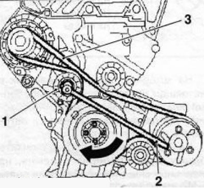
10. Rotate tensioner (see illustration) bolt in the direction of the arrow and loosen the multi-ribbed belt.
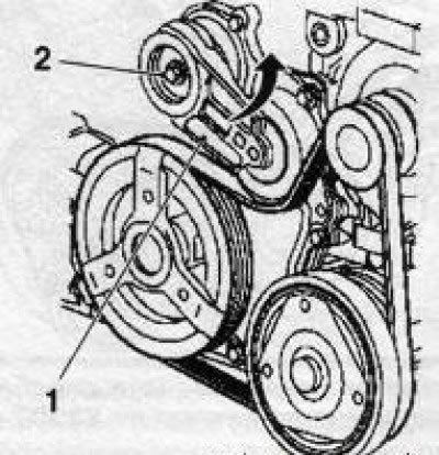
7.10 Loosening the multirib belt (on the example of the Z22YH engine): 1. Tensioner lever; 2. Adjusting bolt
Engines Z20NET/Z22SE/Z22YH
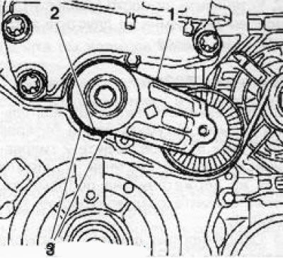
7.11 Checking the position of the lever tensioner (1): 2. Control mark of the tensioner lever; 3. Lever position limit marks
11. After installing the multirib belt, check the position of the tensioner lever (see illustration) - with the belt tensioned, the control mark of the lever must be between the marks of the limit position of the lever.
12. Replace the multirib belt cover and lower the vehicle onto the wheels.
Z32SE engine
13. Disconnect a wire from the negative plug of the storage battery. Release the 2 power steering hydraulic lines from the holders on the subframe, then remove the air intake
14. A feature of this engine is that in order to replace the multirib belt, it is necessary to remove the right engine support
15. Before removing the belt, check the adjustment of the tensioner of the belt tensioner lever must be in position between the stops on the base plate (see illustration)
7.15 Lever (1) tensioner of the multi-ribbed belt must be positioned between the stops (2): 1. Central bolt of the tension roller; 2. Special key
16. Turn the multi-ribbed belt tensioner clockwise with a spanner wrench and remove the belt.
17. Installation is carried out in the reverse order.
Y20DTH/Y22DTR/ Y30DT engines
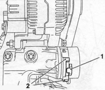
7.18 To loosen the multi-ribbed belt, press the tensioner on the hexagonal tab (1) in the direction of the arrow (using the Y20DTH engine as an example)
18. To loosen the multi-ribbed belt, turn the tensioner by the hexagon (see illustration) counterclockwise, and remove the belt from the pulleys.
Note: The appearance of the Y30DT engine tensioner is slightly different from the illustration.
7.19a Multirib belt tension scheme on Y20DTH / Y22DTR engines
19. Schemes for installing multirib belts are shown on Ref. illustrations.
7.19b Multi-ribbed belt tension diagram on Y30DT engine
Z19DT engines (H)
19. First remove the engine crankcase protection.
20. Loosen the multi-ribbed belt by turning the tensioner with a special key (see illustration 7.20a) in the direction of the arrow, and lock the tensioner in this position with the locking rod (see illustration 7.20b), then remove the belt.
7.20a Loosening the multirib belt (3) (Z19DT engines (H))
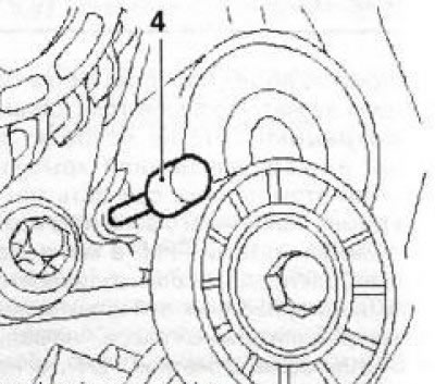
7.20b Installing the stop rod (4) (Z19DT engines (H))
21. Installation is carried out in the reverse order.
Visitor comments