
Attention! Operations to remove the cylinder head should only be carried out in a cold (ambient temperature) engine!
Note: Opel supplies models equipped with petrol engines only to the Russian automotive market through official representative offices. At the time of the release of the Manual, official dealers cannot provide enough materials for the repair of diesel engines. This section provides a detailed description of the procedure for removing the head of gasoline engines. No information is available for some diesel engines.
Engines Z16XE/Z18XE
1. Disconnect the wire from the negative terminal of the battery and remove the engine cover.
2. Remove the toothed belt, at the same time, if there is no need to replace the belt, the right engine support does not need to be removed. Turn out a fixing bolt and remove the directing roller of a gear belt from an inlet camshaft.
3. Drain the coolant.
4. Remove the exhaust system.
5. Disunite sockets of electroconducting of gauges of pressure and level of oil and the gauge of a cranked shaft.
6. Turn out a bolt and remove an arm of an inlet air path Loosen a nut of fastening of the generator.
7. Remove the ignition module.
8. Disconnect the lambda probe wiring, disconnect the 2 hoses of the crankcase ventilation system, disconnect the air preheating hose from the throttle body. Turn out 10 fixing bolts and remove a cover of a head of cylinders. On the Z18XE engine, remove the intake air path.
9. Remove gear wheels of camshafts and remove a back cover of a gear belt.
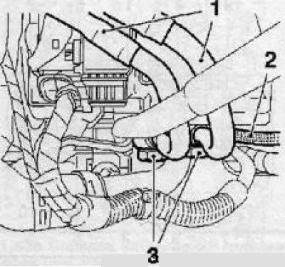
10. Disconnect the fuel tank ventilation system hose. Turn out a fixing bolt and slide the generator back. Loosen the clamp and remove the coolant hose (see illustrations).
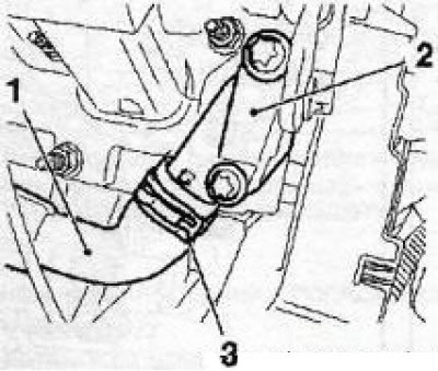
11.10a Loosen clamp (3) and remove the hose (1) cooling system with heat exchanger (2) heater (Z16XE engine)
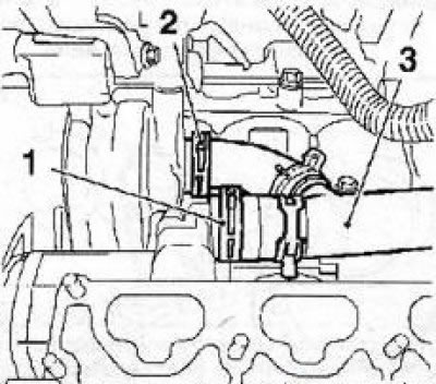
11.10b Loosen clamps (1 and 2) and remove the hose (3) cooling systems (Z18XE engine)
11. Release the pressure in the fuel system through the service fitting using a special tool KM-J34730-91 (see illustration).
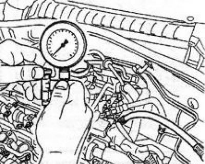
11.11 Installing the KM-J-3473091 (on the example of the Z16XE engine)
12. Disconnect the fuel line from the fuel distribution line using the tool KM-796A (see illustration).
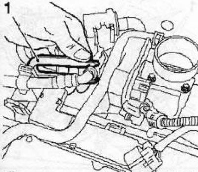
11.12 Disconnecting the fuel line from the fuel distribution line using the KM796-A tool (engines Z16XE/Z18XE)
13. Disconnect the electrical wiring of the engine management system and the ground bus.
14. Remove the power steering vacuum line and heater return hose.
15. Disconnect the upper radiator hose from the thermostat housing.
16. Remove 3 bolts and remove the exhaust manifold heat shield, remove 9 nuts (on the Z18XE engine - 10 nuts) and remove the manifold.
17. Disconnect the crankcase ventilation hose clamp from the cylinder head. If necessary, remove the tube of the dipstick for measuring the level of impellent oil.
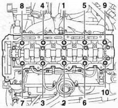
18. Release the head mounting bolts in the reverse order shown in illustration 11.18 in two stages, at the first approach, loosen the bolts by 90°, and at the second - by 180°, then completely unscrew the bolts and remove the block head. Get help from an assistant if necessary.
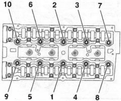
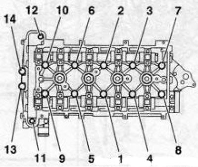
11.19 Order of tightening of a head of the block of cylinders (engines Z16XE/ Z18XE)
19. Installation is made in the reverse order of removal, while replacing all sealing gaskets of the removed components. Tighten the threaded connections to the required torque. When installing the block head, use new fixing bolts. The tightening of the cylinder head bolts is carried out in the sequence indicated on the resist. illustrations in 5 stages: in the first approach, tighten the bolts using a torque wrench, and in subsequent approaches, using a special goniometric device.
Z22YH/Z22SE/Z20NET engines
Note: The procedure for removing/installing drive chains for the Z22YH engine is described below. On the Z20NET engine, instead of the ignition module, 4 ignition coils are installed, separately for each candle, - features (not listed below) dismantling/installation are associated only with these elements. On the Z22SE engine, there may be differences in the location and mounting of some lines and sensors.
20. Disconnect the wire from the negative terminal of the battery, remove the engine cover, remove the probe tube for measuring the level of impellent oil.
21. Remove the right front wheel and the front section of the exhaust system.
22. Release the 2 power steering lines from the holders on the subframe, unscrew the 2 bolts and remove the air inlet bracket.
23. Install the right engine mount remover.
24. Drain the coolant.
25. Set the TDC for the piston of the first cylinder.
26. Remove the camshaft sensor and the right engine support.
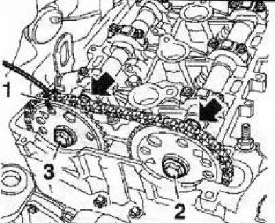
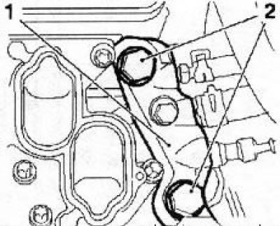
11.27 Secure the exhaust camshaft sprocket with wire (1) unscrew and remove the fixing bolts (2 and 3)
27. Remove the top guide and timing chain tensioner. Secure the exhaust camshaft sprocket with wire (see illustration), unscrew and remove the fixing bolts of both sprockets.
28. Remove the plug and the upper bolt of the timing chain guide (see Section 8).
29. Remove 4 side bolts (1114), then loosen the head mounting bolts in the reverse order shown in fig. 11.31 (10 to 1) in two steps - at the first approach, release the bolts on 90°, and at the second - by 180°then completely unscrew the bolts and remove the block head.
30. Installation is carried out in the reverse order of removal, while replacing all sealing gaskets of the removed components. Tighten the threaded connections to the required torque. When installing the block head, use new fixing bolts. See Section 8 for a description of the chain tensioning procedure.
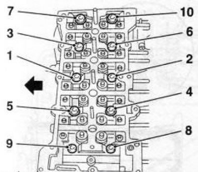
31. The tightening of the cylinder head bolts is carried out in the sequence indicated on the resist. illustrations 1 to 10 in 4 steps: at the first approach, tighten the bolts using a torque wrench, and at subsequent times with a special goniometer. New bolts must be used.
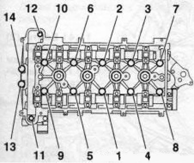
11.31 Cylinder head tightening order (Z22YH engine)
32. Insert 4 bolts into the timing case, having previously lubricated their threads with a fixing compound, and tighten in sequence from 11 to 14 with force 35 Nm (see illustration 11.31).
Note: Before installing the bolts, carefully clean the threads of the holes from the remnants of the old compound.
Z32SE engine
33. Disconnect a wire from the negative plug of the storage battery.
34. Raise the car on a lift, remove the right front wheel and drain the coolant.
35. Remove the multirib belt cover and remove the exhaust system, use the help of one, and if necessary, 2 assistants.
36. Remove graduations (outdoor) distribution shafts.
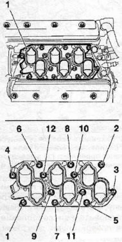
11.37 The order of loosening the bolts of the intake manifold flange (Z32SE engine)
37. Turn out 12 fixing bolts and remove the inlet pipeline flange installed in the collapse of the cylinder block (see illustration) Strictly observe the sequence of releasing the bolts. Close the air intake openings.
38. Turn out 2 fixing bolts and disconnect a flange (see illustration) cooling systems.
11.38 Bolts (2) flange mounting (1) engine cooling systems (Z32SE engine)
39. Disconnect the wiring connectors (see illustration). Remove the 4 engine control module mounting bolts and remove the module. Then turn out 2 bolts and remove an arm of fastening of the module to the block of the engine.

11.39 Disconnect the wiring connectors (arrows) and remove the bolts (1) engine control module mounts (Z32SE engine)
40. Turn out 3 bolts and remove an end plate (see illustration).
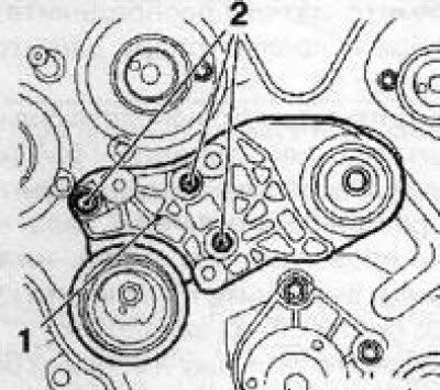
11.40 Bolts (2) end plate fasteners (1) (Z32SE engine)
Attention! The upper toothed belt tensioner must remain on the plate!
41. Remove the bolts (see illustration) and remove the rear timing cover. Remove the dipstick tube for measuring the level of impellent oil.
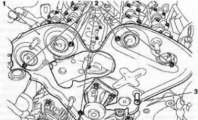
11.41 Bolts (2) back cover fasteners (1) timing (Z32SE engine): 3. Set bolt
42. Loosen the head mounting bolts in the reverse order shown in illustration 11.19 in two steps, at the first approach, loosen the bolts by 90°, and at the second - by 180°, then completely unscrew the bolts and remove the block head. Get help from an assistant if necessary.
43. Installation is carried out in the reverse order of removal, while replacing all sealing gaskets of the removed components. Tighten the threaded connections to the required torque. When installing the block head, use new fixing bolts. The cylinder head bolts are tightened in the sequence shown in Illustration 11.19 in 5 stages: in the first approach, tighten the bolts using a torque wrench, and in subsequent approaches, using a special goniometric device.
Y20DTH/Y22DTR engines
Removal and installation
44. Disconnect a wire from the negative plug of the storage battery.
45. Raise the car on a lift, remove the right front wheel, remove the crankcase protection and drain the coolant.
46. Drain the engine oil.
47. Remove the exhaust system, use the help of one, and if necessary, 2 assistants.
48. Remove the multirib belt. Turn out 2 bolts and remove the belt tensioner.
Attention! The removed tensioner must only be stored in a vertical position, otherwise oil may leak from the hydraulic damper!
49. Turn out 2 bolts and weaken a nut of fastening of the thermofilter of a starter and remove the screen.
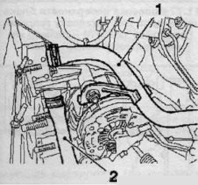
50. Loosen 2 nuts and disconnect the supply lines of the electrical wiring from the generator, disconnect the connector (see illustration) wiring of the engine oil pressure sensor, unscrew the mounting bolt and disconnect the generator cable channel box.
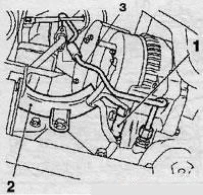
11.50 Generator wiring lines (Y22DTR engine): 1. Wiring connector for engine oil pressure sensor; 2. Generator cable channel box; 3. Oil supply line to the turbocharger
51. Loosen the bolt and nut of the lower mounting of the generator, substitute a suitable container under the engine and disconnect the line (see illustration 11.50) oil supply to the turbocharger.
52. Turn out the top and bottom bolts of fastening of an arm of the inlet pipeline and disconnect it.
53. Remove 2 mounting bolts, loosen the fastening clamps and remove the cooling system hose located on the front (in the direction of the car) side of the engine. Remove the coolant hose from the thermostat housing.
54. Lower the car and remove the engine cover (see section 2).
55. Release from the holders and remove the vacuum line of the brake booster, loosen the fastening clamps, unscrew the 2 fixing bolts and remove the upper pipe of the turbocharger air duct.
56. Disconnect with tool KM-717 (see illustration 7.6 in Chapter 5) electrical wiring from glow plugs.
57. Remove the air cleaner.
58. After loosening the fastening clamps, disconnect the upper radiator hose and heater hoses. Disconnect the wiring from the coolant temperature sensor.
59. Disconnect the oil hose (see illustration), unscrew the 2 bolts, disconnect the quick couplings using the tool KM-796 and disconnect the fuel lines.
11.59 Remove the fixing bolts (3) and disconnect the fuel lines (1) (Y22DTR engine) 2 Oil hose
60. Disconnect the 2 vacuum lines from the vacuum reservoir, disconnect the electrical wiring from the air conditioning pressure sensor-switch, the cable duct and the cooling system line from the engine head.
61. Turn out 2 bolts and disconnect electroconducting of the engine control module.
62. After unscrewing the mounting bolts, remove the heat shields of the intake duct and exhaust manifold.
63. Disconnect the oil return line (see illustration) turbocharger, - while the exhaust manifold must not be removed.

11.63 Oil return line (1) turbocharger (Y22DTR engine): 2. Exhaust manifold
64. Loosen the generator and move it back. Release a nut and disconnect electroconducting from a starter.
65. After loosening the clamps, disconnect 2 hoses (see illustration) cooling systems.
11.65 Hoses (1 and 2) cooling systems (Y22DTR engine)
66. Loosen the fastening clamps and remove the connecting hose of the turbocharger air duct and the inlet pipe.
67. Disconnect the wiring from the exhaust gas recirculation valve (EGR).
68. Disconnect all supply lines, unscrew 4 bolts and remove the inlet pipe (see illustration).
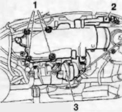
11.68 Bolts (1) intake manifold fittings (Y22DTR engine)
69. Turn out nipple and fixing bolts and disconnect 4 fuel lines of injectors, turn out 4 bolts and remove the vacuum pump. Disconnect the remaining connectors of the electrical wiring installed on the head of the sensor unit and some other lines that interfere with the removal of the head.
70. Having unscrewed 8 bolts and having removed washers remove a cover of a head of cylinders. Raise the car on a lift and remove the injection pump sprocket cover.
Attention! When installing the cover, sealant must be applied to its reverse side! To separate the cover, use a wide spatula or other suitable tool, do not apply great force, otherwise the deformation of the cover will lead to oil leakage in the future!
71. Turn out a bolt of fastening of an arm of the K/V compressor, release from holders on a stretcher 2 lines of the amplifier of a wheel and establish adaptation for removal of the right support of the engine.
72. Remove the camshaft sensor and remove the right engine mount.
73. Remove the camshaft sprocket.
74. Remove 4 additional bolts (see illustration), then loosen the head mounting bolts in the order shown in two steps - on the first approach, loosen the bolts by 90°, and at the second - by 180°then completely unscrew the bolts and remove the block head. Get help from an assistant if necessary.
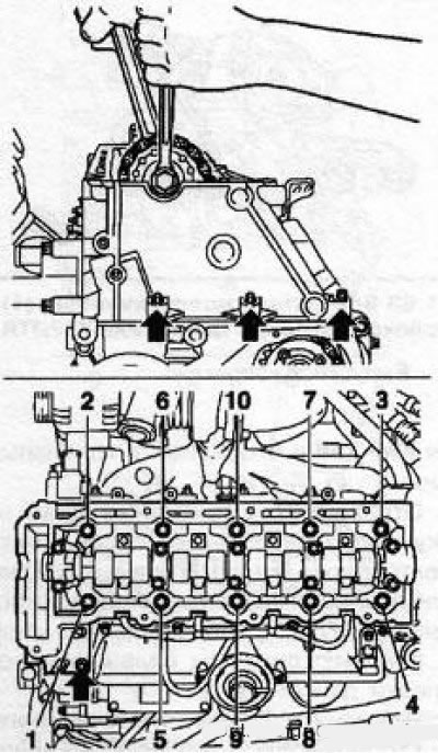
11.74 The order of releasing the cylinder head bolts (Y22DTR engine) - arrows indicate additional bolts
75. Before installing the head, it is necessary to perform a check procedure (see below) and choose the appropriate gasket.
11.76 The order of tightening the cylinder head bolts (Y22DTR engine)
76. Installation is carried out in the reverse order of removal, while replacing all sealing gaskets of the removed components. Tighten threaded connections with the required force. When installing the block head, use new fixing bolts. The tightening of the cylinder head bolts is carried out in the sequence indicated on the resist. illustrations in 6 stages: in the first approach, tighten the bolts using a torque wrench, and in subsequent approaches, using a special goniometric device. Additional head bolts are tightened in 3 steps.
Examination
77. After removing the head, it is necessary to clean the mating surfaces of the head and the engine block and check them for surface deformation using a tool with a smooth straight edge (see illustration).
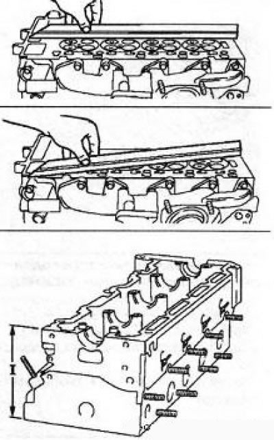
11.77 Checking the surface of the cylinder block for head installation (Y22DTR engine) - size «I» should be 140 mm
78. For this engine, the thickness of the new cylinder head gasket is of particular importance. To obtain the optimal volume of the combustion chamber, the engine pistons protrude slightly on the surface of the block at their TDC. To ensure that the piston and timing valves do not touch during operation, it is necessary to provide an appropriate clearance.
79. To measure the height of the protrusion of the piston above the surface of the block, it is necessary to install devices on the surface of the block (see illustration) and expose «0» on the scale of the plunger-type meter at the moment when the meter probe is in contact with the surface of the block.

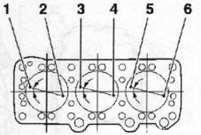
11.79 Piston protrusion measurement and point (3-6) measurements: 1. Meter MKM-571-V; 2. Adaptation KM-301
80. Measure the protrusion of all pistons in turn, measuring at two points on each piston (see illustration 11.79) - for measurement it is necessary to select points (3 and (4) or another pair (5) And (6). When measuring, rotate the crankshaft smoothly to determine the highest lift point. Based on the results of all measurements, select the largest amount of piston lift. At the end of the procedure, turn the crankshaft to 60° counterclock-wise.
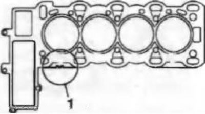
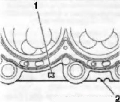
11.81 Marking (1) cylinder head gaskets (motors Y20DTH/Y22DTR)
81. Determine the thickness of the new gasket according to the data in the table. Appropriate labeling (notches) applied to pads (see illustration).
Z19DT engines (H)
11.82a The procedure for tightening the cylinder head (Z19DTH engine) - the arrow indicates the direction of movement of the car
11.82b Cylinder head tightening order (Z19DT engine)
82. The tightening of the cylinder block cooking bolts is carried out in the sequence indicated on the resist. illustrations in 5 stages: in the first and second approaches, tighten the bolts using a torque wrench, and in subsequent approaches, using a special goniometric device.
Y30DT engine
83. Remove the camshaft housing, first one, then the other cylinder head.
84. In addition to the above work, in the process of preparing the heads for removal, it is necessary to drain the engine oil, remove the multi-ribbed belt and its guide roller, remove 12 valve lifters, loosen the generator and move it back. Carefully inspect the heads, make sure that nothing prevents their removal.
85. Turn out bolts of fastening of heads in an order, the return shown on an illustration 11.88, and remove a corresponding head.
Attention! The bolts have different lengths - remember or mark the places of their installation!
11.86 Piston protrusion measuring points (Y30DT engine)
86. Before installing the heads, it is necessary to clean the head and block. Check mating surfaces and piston protrusion. The test procedure is fundamentally the same as described above for the Y20DTH/Y22DTR engines - the same tools are used. The measuring points are shown on the resist. illustrations.
11.87 Marking (1 and 2) cylinder head gaskets (Y30DT engine)
87. Determine the thickness of the new gasket according to the data in the table. Appropriate labeling (notches) applied to pads (see illustration). On right head gaskets (13-5 cylinders) marked «R», and for the left head - «L».
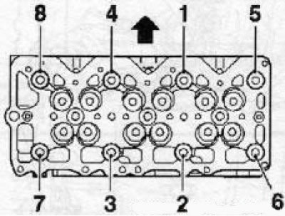
11.88 The order of tightening the cylinder head bolts (Y30DT engine) - the arrow indicates the side of the intake camshafts
88. Installation is carried out in the reverse order of removal, while replacing all sealing gaskets of the removed components. Tighten the threaded connections to the required torque. When installing the block head, use new fixing bolts. The tightening of the cylinder head bolts is carried out in the sequence indicated on the resist. illustrations in 5 stages: in the first approach, tighten the bolts using a torque wrench, and in subsequent approaches, using a special goniometric device. Positions 1 to 4 should be occupied by long bolts, and positions 5 to 8 should be short!
Attention! Bolts of different lengths reach different angles!
- 1st reception: Bolts 1 to 8 - 39 Nm
- Step 2: Bolts 1 to 4 - 130°
- Step 3: Bolts 5 to 8 - 110°
- Step 4: Bolts 1 to 4 - 130°
- Step 5: Bolts 5 to 8 - 110°
Visitor comments