
2. Follow the correct sequence when removing bearing caps. The fasteners of the covers should be released evenly, in a spiral from the edges inward, in several steps, 1-0.5 turns per approach. On engines whose camshafts are mounted on bearings cast directly into the cylinder head, special care must be taken when loosening the fasteners and removing the bearing caps. Careless handling can damage the camshaft bearings or the bearing cover. If at least one cover is broken, you will have to change the entire head of the block - in the manufacture of covers, they are processed together with the head and individually to the spare parts market. not supplied! Installation and tightening of the fasteners of the covers is carried out in the reverse order of their removal.
Engines Z16XE/Z18XE
Removing
3. On models with timing belt drives, to remove the camshafts, you must first remove the toothed belt
Before loosening the toothed belt, bring the engine out of TDC by turning the crankshaft at 60° counterclockwise so that neither piston is at TDC.
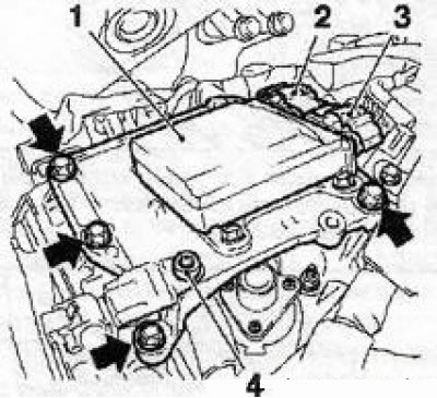
4. Before removing the cylinder head cover, first remove the ignition module. Disconnect all wiring connectors and hoses. Turn out fixing bolts and remove a cover.
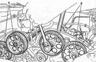
5. Remove gear wheels of camshafts.
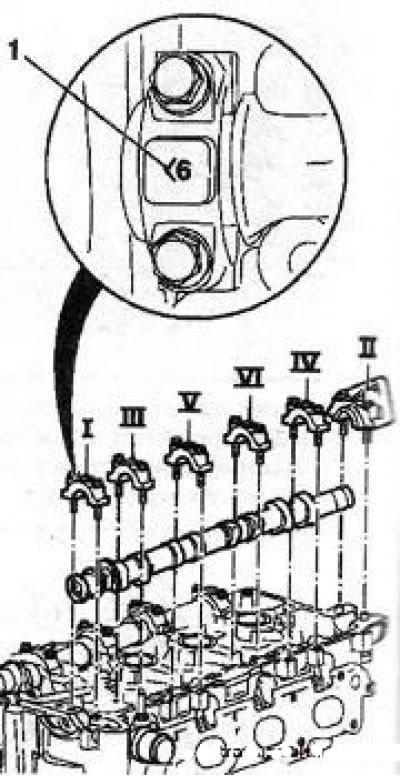
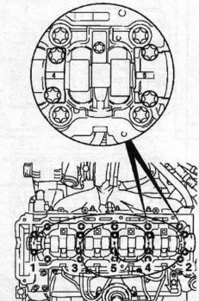
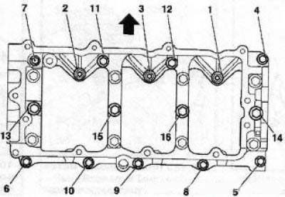
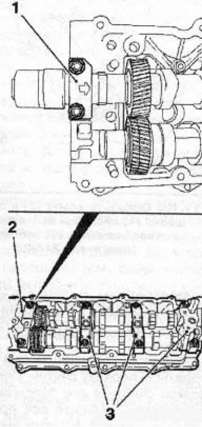
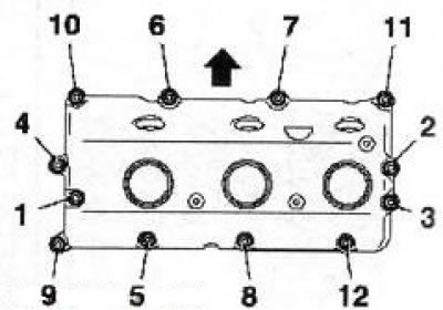
10.6 The sequence of releasing the fixing bolts of the upper covers of the camshaft support bearings
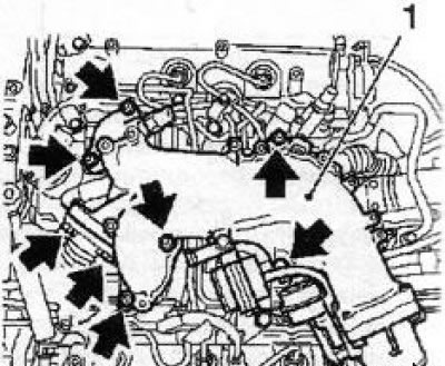
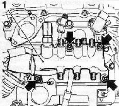
6. Remove camshafts. first of all, the exhaust camshaft is removed: moving in a spiral from the edges inward (in the sequence shown in Fig. illustrations), in several stages, evenly loosen the bolts securing the upper shaft covers, then completely unscrew the bolts.
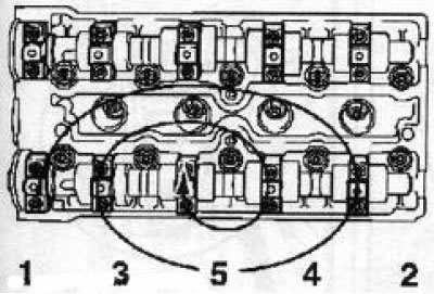
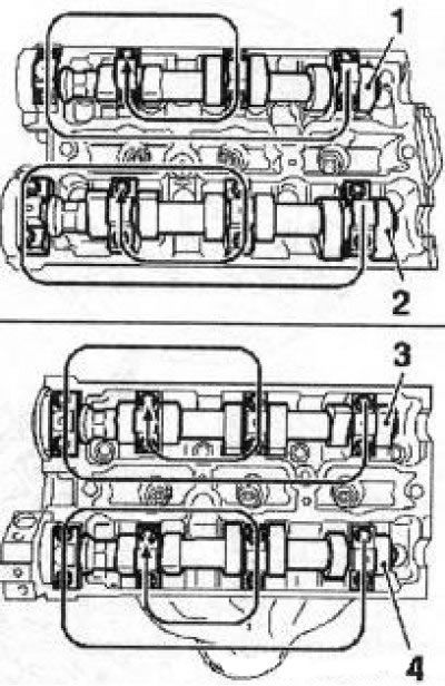
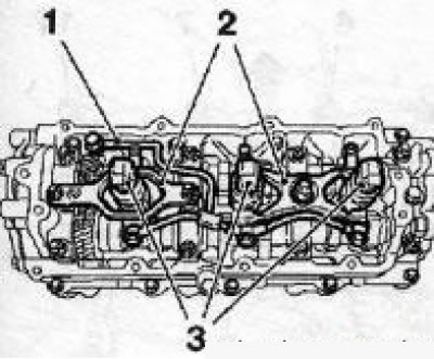
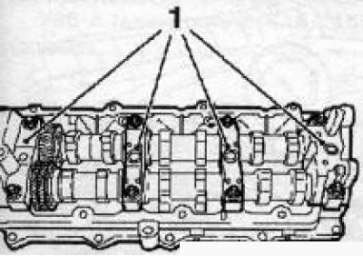
7. When removing the upper covers of the camshafts, pay special attention to the numbering of the covers during assembly, they must be installed strictly in their original places, the numbering of the covers of the camshaft support bearings is shown in Ref. illustrations. If for any reason there are no marks, they must be applied independently using a marker.
10.7 Numbering of camshaft bearing caps (Z18XE engine)
8. Raise the camshaft and remove it from the engine, carefully remove the oil seal.
9. Acting in a similar manner, remove the inlet camshaft - when installing the shafts must be installed only in their places.
10. Prepare 16 small clear plastic bags or clean plastic cups and label them according to the valve numbers. Using the tools, remove the pushers from the head and place them in the appropriate cups.
Note: To prevent oil leakage from the hydraulic tappets (with appropriate equipment) lay the pushers with the working ends up.
Examination
11. Wipe the timing parts with a clean rag and carefully examine the condition of the bearing journals and camshaft cams. In case of scoring, scratches or signs of wear of the camshafts, they must be replaced together with the hydraulic pushers. If the thrust bearings are worn or damaged, the cylinder head assembly must be replaced (see paragraph 5).
12. Alternately laying the camshafts in prisms, using a plunger-type dial gauge, determine the amount of their radial runout (on bearing journals). If the measurement results are out of range, the camshaft must be replaced.
13. Check up a condition of pushers and their landing sockets in a head. If there are signs of excessive wear of the working surfaces, cracks, scoring and other damage, replace the pushers.
Note: The tappets must also be replaced if the operation of the valve mechanism has recently been accompanied by an increased background noise.
Installation
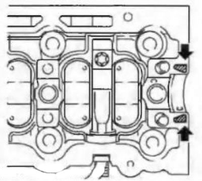
14. Before installation, lubricate the mating surfaces of the camshafts with molybdenum-containing grease (with content MoS2). Clean the mating surfaces of the guides (front) bearings (see illustration), apply fresh sealant (Green colour).
10.14 Places for applying sealant for installation of thrust bearing caps - indicated by arrows
15. Install the intake valve shaft first and tighten the mounting bolts in the reverse order of release (see illustration 10.6), then install the exhaust valve shaft.
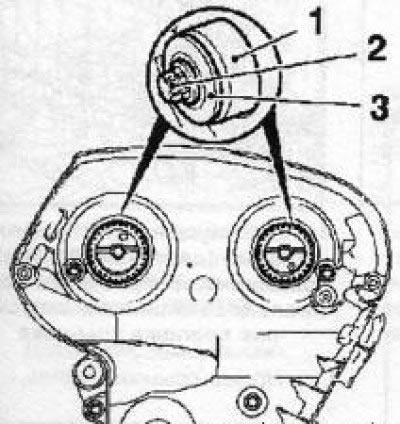
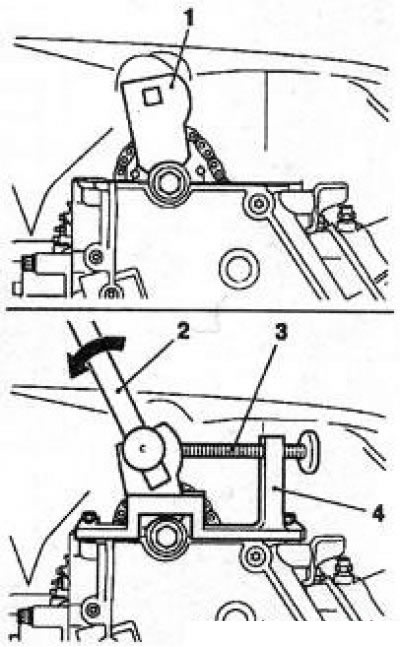
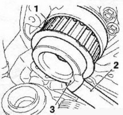
10.16 Installing the camshaft seals (on the example of the Z16XE engine): 1. Adaptation KM-422; 2. A bolt of fastening of a gear pulley of a camshaft; 3. Washer
16. Press in new oil seals using the tool KM-422 (see illustration) or other suitable tool. Before installation, lubricate the outer surfaces of the oil seals with silicone grease (white color).
17. Before installing the cylinder head cover, clean all mating surfaces, replace the gaskets on the cover and apply fresh sealant (black color). Establish a cover on a head of cylinders and tighten fixing bolts with the demanded effort.
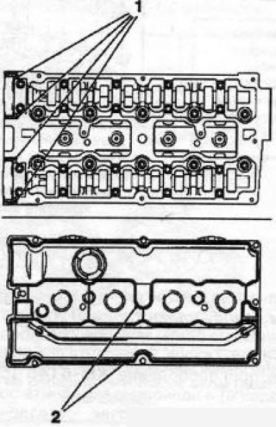
10.17 Replacing cylinder head cover gaskets (Z18XE engine): 1. Places for installing gaskets; 2. Sealing surface
18. Establish cogwheels/asterisks of camshafts.
19. Adjust the valve timing and install the toothed belt (with appropriate equipment). Reinstall all removed components.
Features for Z22YH/Z22SE/Z20NET engines
Note: The difference between the Z20NET engine is the installation of a slightly different ignition system (see chapter 5) and related dismantling operations. Otherwise, the procedure for removing / installing camshafts is similar to that described below.
20. Set the piston of the first cylinder to the TDC position, remove the upper timing chain guide (see illustration 8.76 of Section 8) and loosen the timing chain by unscrewing the chain tensioner (see illustration 8.77).
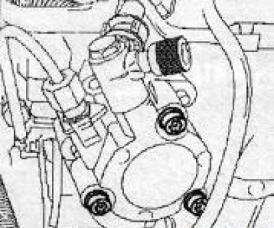
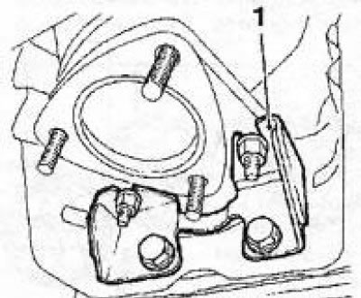
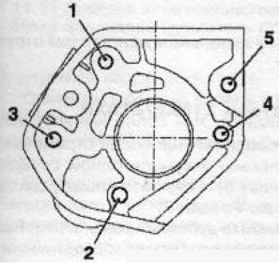
10.21 High pressure petrol pump (Z22YH engine)
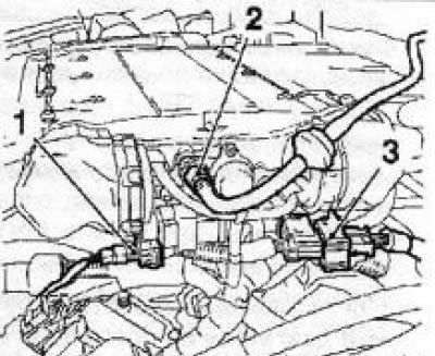
21. Turn out 3 bolts and remove the petrol pump of a high pressure (see illustration). Remove the camshaft sensor.
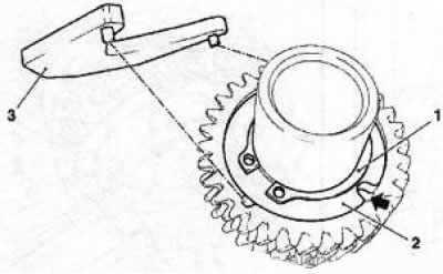
22. Holding the camshafts from turning with an open-end wrench by the hex part of the shaft (see illustration), loosen the fastening bolts of the camshaft sprockets, install the special toolKM-6148 and completely unscrew the sprocket mounting bolts - the asterisks should remain on the guides of the installed fixture.
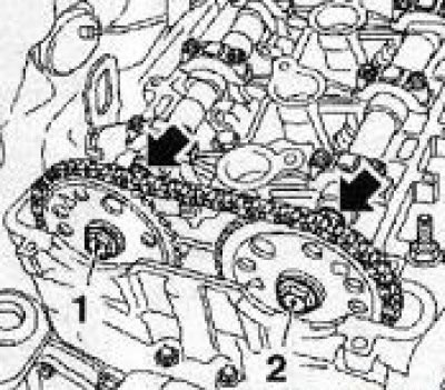
10.22 Bolts (1 and 2) camshaft sprockets fastening (Z22YH engine) the arrows indicate the hexagonal sections of the shafts
23. Please note - the exhaust shaft has 5 bearings, and the intake shaft - 6 (see illustrations). All upper camshaft bearing caps are numbered. Unscrew the fixing bolts of the exhaust camshaft support bearing caps, remove the caps and remove the shaft. Then remove the intake camshaft.
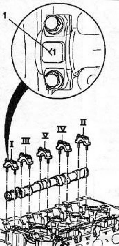
10.23a Final camshaft (Z22YH engine) - Roman numerals indicate the sequence of releasing the cover fasteners: 1. Cover number
10.23b Inlet distributor (Z22YH engine) Roman numerals indicate the sequence of releasing fasteners: 1. Cover number
24. Before installation, lubricate the mating surfaces of the camshafts and hydraulic tappets with molybdenum grease (with content MoS3). Install intake valve shaft first, apply sealant strips (gray color) on mating surfaces (see illustration) under the pilot bearing cap and tighten the mounting bolts in the reverse order of loosening, then install the exhaust valve shaft.
10.24 Installing the pilot bearing (Z22YH engine) The arrows indicate the places where the sealant was applied
25. Install the camshaft sprockets and secure them with new bolts, adjust the valve timing and reinstall all removed components. When installing the timing chain tensioner, follow the instructions in Section 8.
Features for Z32SE engine
26. Remove the toothed belt.
27. Relieve pressure in the fuel supply system, disconnect the electrical wiring and lines of the fuel tank ventilation systems and the fuel supply line.
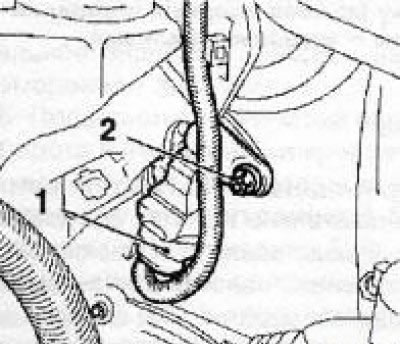
28. Disconnect the crankcase ventilation hose from the throttle valve module and the engine cooling hose from the expansion tank. Disunite connectors of electroconducting and disconnect a line of the vacuum amplifier of brakes.
10.28 Line (2) vacuum brake booster (Z32SE engine): 1, 3. Wiring connectors.
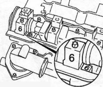
29. Release the hose of the crankcase ventilation system from the holder, unscrew the 6 fixing bolts (see illustration), disconnect the coolant hose and remove the charge chamber. Close the intake air ducts with suitable plugs.
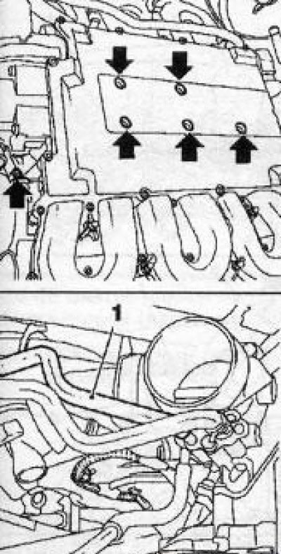
10.29 Bolts (indicated by arrows) pressure chamber mountings (Z32SE engine): 1. coolant hose
30. Remove the ignition modules, and then turn out the bolts and remove the cylinder head covers.
31. Remove the camshaft sensor and, holding the shafts from turning by the hexagonal sections with an open-end wrench, remove the gears from them (see illustration).
10.31 Removing gears (Z32SE engine): 1. Camshafts 1-3-5 cylinders; 2. Camshafts 2-4-6 cylinders
32. Turn out bolts of fastening of covers and remove camshafts at first 1-3-5 cylinders, and then 2-4-6 cylinders (see illustration).
10.32 Procedure for removing camshafts (Z32SE engine): 1. Inlet valve shaft 1-3-5 cylinders; 2. Shaft of final valves 1-3-5 cylinders; 3. Intake valve shaft 2-4-6 cylinders; 4. Exhaust valve shaft 2-4-6 cylinders
Note: The exhaust shafts must be removed first.
33. When installing, apply sealant (black color) on mating surfaces (see illustration 10.14) support covers (front) bearings, install the covers and tighten them in the reverse order of removal. Replace the camshaft seals, press them in using the KM-422 tool and the gear wheel mounting bolts.
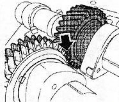
34. Install the gears on the shafts. When installing gears, the crankshaft of the engine should take a position in which the piston of the first cylinder has not reached about 60 'to TDC - the position of the gear marks is shown in the resist. illustrations.
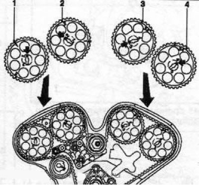
10.34 Position of gear marks when mounted on camshafts (Z32SE engine)
35. Install a toothed belt and adjust the valve timing.
36. Further installation is carried out in the reverse order of removal.
Features for Y20DTH/Y22DTR engines
37. Remove the engine cover, separate the vacuum pump housing from the cylinder head, remove the multirib belt and belt tensioner. Set the TDC position for the piston of the first cylinder and fix it.
38. Remove tensioner (see illustration) single strand chain, heat the 2 fixing bolts with hot air and remove them. Remove the upper single row chain guide.
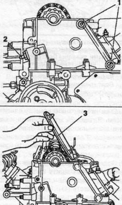
10.38 Removing the guide (3) single row chain (engine Y20DTH/ Y22DTR) 1 Fixing bolts: 2. Single row chain tensioner
39. Remove the TDC test tools, unscrew the fixing bolt and remove the camshaft sprocket.
40. Check Room Availability (see illustration) on the camshaft bearing caps, mark yourself if necessary. Gradually loosen and unscrew the mounting bolts in the order shown in the illustration, remove the covers.
10.40 Procedure for removing the camshaft bearing caps (engine Y20DTH/Y22DTR)
41. Installation is carried out in the reverse order of removal. Apply sealant before installing covers (Green colour) on the mating surfaces of the thrust bearing (see illustration).
10.41 Places of application of sealant are indicated by arrows (engine Y20DTH/Y22DTR)
42. After installing the upper guide chain, it is necessary to set the TDC position for the piston of the first cylinder, for which install the tool KM-933 (see illustration), press the sprocket counterclockwise and secure in this position with the fixing bolt. Install fixture KM-927 into the injection pump drive sprocket hole. If the fixture is not installed, align the holes by loosening the fixing bolt. Install the chain tensioner and tighten it to the required torque.
Features for Y30DT engine
Note: The design feature of the timing of this engine is that the support bearings are made on a separate timing housing. If necessary, they can be replaced without changing the cylinder head.
Note: Preparatory work to gain access to the camshafts is quite laborious, it will require the removal of a large number of small parts, hoses, lines and sensors. These operations are given in abbreviated form, if necessary, contact an Opel workshop.
10.42 Installing the KM-933 fixture (4) for setting TDC (motors Y20DTH/Y22DTR): 1. Fixture adapter; 2. Special key (lever); 3. Fixing bolt
43. Remove the top cover of the engine, disconnect and remove the battery from the pallet, remove the air cleaner, remove the cover of the expansion tank.
44. Raise the car on a lift, remove the engine crankcase protection and drain the coolant.
45. Remove the exhaust system and catalytic converter mounting bracket (see illustration).
10.45 Bracket (1) catalytic converter (Y30DT engine)
46. Remove the air cleaner, fuel filter and expansion tank.
47. Disconnect and remove all lines mounted on top of the engine, such as cooling system hoses, power steering vacuum lines, fuel lines, crankcase ventilation system lines, turbocharger oil lines, intake air path elements and exhaust manifold, vacuum pump, as well as an electronic control module engine and other sensors mounted on the engine heads. The fastening of some of the most important elements is shown in Ref. illustrations.
10.47a Removing the module (1) engine control (Y30DT engine) the arrows indicate the mounting bolts of the module bracket: 2, 3. Wiring connectors; 4. Bolt of fastening of the holder of the fuel line
10.47b Removing the intake air duct (1) (Y30DT engine) the arrows indicate the fastening elements of the tract
10.47c Removing the fuel distribution line (1) (Y30DT engine) - Arrows indicate mounting bolts
48. Install the special tool KM-6352 and remove the right engine epora, and then the timing belt. Remove the rear lifting eye.
49. Turn out 12 fixing bolts and remove a cover of the case of camshafts/heads of 1-3-5 cylinders.
50. Disconnect and remove lines (see illustration) lubrication systems. Loosen 3 nuts and remove 2 mounting brackets and injectors.
10.50 Removing the nozzles (3) 1-35 cylinders (Y30DT engine) 1 Lubrication system lines: 2. Mounting brackets
51. Remove 13 screws and 3 bolts strictly following the established sequence (see illustration) and remove the camshaft housing together with the shafts.
10.51 The order of loosening the screws and nuts of the camshaft housing 1-3-5 cylinders (Y30DT engine) - the arrow indicates the installation side of the intake camshaft
Note: The bolts have different lengths, please remember or mark where they are installed.
Turn out 2 bolts and 2 nuts and remove a forward cover of the case of camshafts.
52. With the help of special devices (see illustration) loosen and remove the camshaft drive gear bolt. Get help from an assistant if necessary.
10.52 Removing the gear (1) camshaft drive (Y30DT engine) 2 Adaptation KM-956-1: 3. Adaptation KM-6379
53. Remove 5 bolts and remove the gear housing, remove 8 bolts, remove 4 covers (see illustration) support bearings and remove the camshafts.
10.53 Lids (1) support bearings for camshafts 1-3-5 cylinders (Y30DT engine)
54. If necessary, secure the exhaust camshaft in a vice, remove the retaining ring (see illustration), compensation washers and spring. Remove the compensation gear from the shaft.
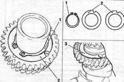
10.54 Dismantling the exhaust camshaft (Y30DT engine): 1. Optional; 2. Front; 3. Rest
55. The procedure for removing camshafts 2-4-6 cylinders is almost the same as described above. The difference is that the shafts have 5 bearing caps. It is necessary to first loosen the bolts securing all covers, then remove the front cover (2) (see illustration). Remove 2 screws and remove cover (1) additional bearing. Remove remaining covers.
10.55 Camshaft bearing caps 2-4-6 cylinders (Y30DT engine)
56. Installation is made in the reverse order of removal. Clean all mating surfaces before installation. Replace all gaskets, apply fresh sealant instead of removed. Tighten the bolts of the camshaft drive gear mounting housing 1-3-5 cylinders (see illustration). The bolts of the gear housing of 2-4-6 cylinders are tightened in a mirror order. Do not forget to replace the camshaft drive seals, press in new seals using the appropriate tool and gear mounting bolts.
10.56 The order of tightening the fixing bolts of the mounting housing of the gear wheel of the camshaft drive 1-3-5 cylinders (Y30DT engine): 1. Retaining ring; 2. Compensation washers; 3. Spring
57. If the exhaust camshaft was disassembled, install the spring in place, make sure it is properly seated. Install the wear washers so that the notch on the washer aligns with the mounting hole (see illustration), and using a special tool, turn the compensation gear until all the mounting holes are aligned and fix it from turning by installing a punch with a diameter of approximately 3 mm.
10.57 Assembling the exhaust camshaft (Y30DT engine) - the arrow indicates the mounting hole: 1. Retaining ring; 2. Compensation washer; 3. Adaptation KM-6378
58. When installing the shafts in the housing, the marks on the gears must match (see illustration 10.58a). After installing the shafts, do not forget to remove the drift from the exhaust shaft gear. Tightening the screws/bolts of the camshaft housing must be done in the reverse order of loosening them (see illustration 10.51). The order of a tightening of covers of cases of camshafts is resulted on an illustration 10.58b.
10.58a When setting a label (indicated by an arrow) on the camshaft gears must match (Y30DT engine)
10.58b Tightening order of the camshaft housing cover fixing bolts (Y30DT engine) the arrow indicates the installation side of the intake shaft
Visitor comments