OpelBook.ru
Cars AvtoVAZ Cars Mitsubishi Cars BMW Cars Mercedes Cars Nissan Cars Toyota Cars Chevrolet
English Русский
Български
Беларускі
Український
Српски
Hrvatski
Română
Polski
Slovenský
Magyar
 |  Sitemap  |  Contacts  |    


Main Astra Corsa Insignia Kadett Omega Vectra Zafira Others Articles
Astra F (1991-1998, petrol) Astra G (1998-2004, petrol) Astra G (1998-2004) Astra H (2004-2009) Astra J (2009-2015, petrol)
  • Main
  • Astra
  • Astra G
  • Power unit
  • SOHC gasoline engines
  • Removal, inspection and installation of valve drive components

Removal, inspection and installation of valve drive components (Opel Astra G)

            0

Contents: Carrying out work using the Opel…⬇ Carrying out work without using the…⬇

Carrying out work using the Opel KM-565 device


Removal


1. Using the special device KM-565 (or an equivalent substitute), the valve drive levers and valve clearance compensators can be removed without first removing the camshaft.

2. Set the parking brake, then jack up the front of the vehicle and place it on supports. Remove the right front wheel, and if so equipped, also remove the crankcase guard.

3. Remove the timing cover (see Removal and installation the timing cover).

4. Turn the crankshaft in the normal direction by the pulley bolt until the cam of the first valve, the drive components of which are subject to maintenance, turns with the working lug upward.

5. Secure the device on top of the valve timing case, aligning its tip with the end of the corresponding valve stem. Screw the pin of the device into one of the housing bolt holes until the valve is recessed enough to enable the lever of its drive to be removed from under the camshaft. Now you can remove the hydraulic compensator and remove the oil deflector cap.

6. Carefully check the status of all components (see below Examination), - replace worn or damaged ones.

Installation


1. Lubricate the valve drive lever and its clearance compensator with clean engine oil and insert the latter into its seat in the cylinder head. Install the valve drive lever in its place, making sure that its ends are correctly positioned on the end of the valve stem and the surface of the hydraulic compensator. Carefully remove the device.


2. Proceed in a similar manner to service the remaining valve drive components.

Carrying out work without using the Opel KM-565 device


Removal


1. The inability to use a special device leads to the need to dismantle the camshaft assembly with the timing mechanism housing in order to provide access to the components to be serviced.

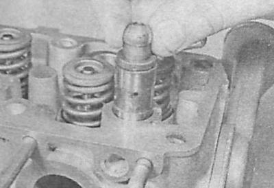
2. After removing the valve timing case, prepare 8 clean plastic bags or plastic cups, marking them in the order of the valve numbers (you can also use a large box divided into eight separate sections). Remove the valve drive levers, oil seals and hydraulic compensators one by one and place them in appropriately marked containers.
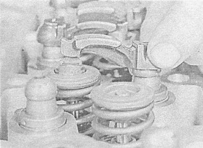
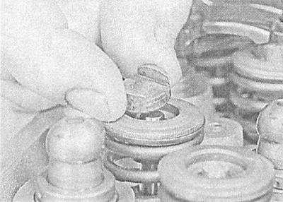
2. After removing the valve timing case, prepare 8 clean plastic bags or plastic cups, marking them…


2. After removing the valve timing case, prepare 8 clean plastic bags or plastic cups, marking them…


2. After removing the valve timing case, prepare 8 clean plastic bags or plastic cups, marking them…


Installing the valve drive levers in an arbitrary order will result in a violation of the correspondence between the shape and degree of their wear and the wear of the working surfaces of the camshaft cams!


Examination


1. Check the surfaces of the valve drive levers that contact the cams for signs of wear and mechanical damage - replace defective levers. If defects are found in the levers, also check the condition of the working surfaces of the corresponding camshaft cams - they will most likely also be damaged or worn out.

[Article posted on an online resource: opelbook]

2. Check the condition of the oil deflector caps and make any necessary replacements.

3. If there is no certainty in determining the condition of the hydraulic compensators, they should also be replaced - checking the correct functioning of the compensators is not possible.

Installation


1. Lubricate the hydraulic compensators and the walls of their mounting seats with clean engine oil. Install the compensators in their original places.

2. Install the oil deflector caps on the valves.

3. Lubricate the valve drive levers with clean engine oil and install them in their original places, checking the correct fit on the compensators and valve stems.

4. Finally, install the timing case with the camshaft inserted into it (see Removal and installation the cylinder head).


This article is available at russian, bulgarian, belarusian, ukrainian, serbian, croatian, romanian, polish, slovak, hungarian
Checking the article: Pavlovsky Nikolay

Share information:

Previous articles
Opel Astra G: SOHC gasoline engines
Next articles

Removal, condition check and installation of the camshaft with the timing mechanism housing
Replacing the camshaft seal
Removal and installation the timing belt tensioner and timing drive gears
Removal and installation the timing belt
Removal and installation the timing belt cover
Removal and installation the crankshaft pulley
Removal and installation the cylinder head
Removal and installation the oil pan
Removal, maintenance and installation of the oil pump
Removal, checking condition and installing flywheel/drive disk
Replacing crankshaft seals
Checking the condition and replacing the powertrain suspension supports


See similar ones from other Opel car manuals:
▶ Removal and installation of camshafts and valve lifters,… Opel Corsa C (2000-2006)
▶ Adjusting clearances in the valve drive mechanism Opel Kadett E (1984-1995)
▶ Removal and installation of gear shift drive components… Opel Vectra C (2002-2008)
▶ Precautions to prevent the collapse of the vehicle or its… Opel Insignia A (2008-2017)
▶ Checking the condition of the auxiliary drive belt — every… Opel Omega A (1986-1993)
Link to this page in different formats

Visitor comments


No comments yet


How much will 50 + 49 =


Astra J (2009-2015, petrol) 
  • General information
  • Vehicle device
  • User manual
  • Faults en route
  • Maintenance
  • Power unit
  • Engine repair
  • Cooling and lubrication system
  • Engine power system
  • Exhaust system
  • Transmission
  • Clutch
  • Car gearbox
  • Drive shafts
  • Chassis
  • Front suspension
  • Rear suspension
  • Steering
  • Brake system
  • Wheels and tires
  • Body
  • Exterior
  • Interior
  • Doors and windows
  • Body Care
  • Heating and air conditioning
  • Security systems
  • Electrical equipment
  • Equipment and devices
  • Lighting and signaling
  • Power devices
  • Electrical circuits
Astra H (2004-2009) 
  • General information
  • Introduction to the guide
  • Troubleshooting
  • User manual
  • Maintenance
  • Power unit
  • Engine repair
  • Cooling and heating
  • Power and exhaust system
  • Ignition system
  • Launch and charge system
  • Transmission
  • Mechanical gearbox
  • Automatic gearbox
  • Drive shafts
  • Chassis
  • Brake system
  • Car suspension
  • Steering
  • Body
  • Interior
  • Exterior
  • Electrical equipment
  • Equipment and devices
  • Electrical circuits
Astra G (1998-2004) 
  • General information
  • Introduction to manual
  • User manual
  • Maintenance
  • Power unit
  • SOHC gasoline engines
  • DOHC gasoline engines
  • Diesel engines 1.7 and 2.0
  • Engine repair
  • Cooling system
  • Supply system
  • Injection system (gasoline)
  • Injection system (diesel)
  • Exhaust system
  • Charge and launch system
  • Ignition system (gasoline)
  • Preheat system (diesel)
  • Transmission
  • Manual gearbox
  • Automatic gearbox
  • Clutch
  • Drive shafts
  • Chassis
  • Brake system
  • Wheel suspension
  • Steering
  • Body
  • Exterior
  • Interior
  • Doors and windows
  • Ventilation and heating
  • Electrical equipment
  • Equipment and devices
  • Electrical circuits
Astra G (1998-2004, petrol) 
  • General information
  • User manual
  • Car care
  • Maintenance
  • Power unit
  • Single shaft engines
  • Twin shaft engines
  • Engine repair
  • Cooling and heating
  • Fuel and exhaust systems
  • Starting and charging system
  • Ignition system
  • Transmission
  • Clutch
  • Mechanical gearbox
  • Automatic gearbox
  • Drive shafts
  • Chassis
  • Brake system
  • Car suspension
  • Steering
  • Body
  • Interior
  • Exterior
  • Electrical equipment
  • Equipment and devices
  • Wiring diagrams Opel Astra
  • Wiring diagrams Opel Zafira
Astra F (1991-1998, petrol) 
  • General information
  • Maintenance
  • Power unit
  • Engine in car
  • Engine removed
  • Cooling system
  • Heating and ventilation
  • Fuel supply (carburetor)
  • Fuel supply (injector)
  • Emission control
  • Ignition system
  • Transmission
  • Clutch
  • Mechanical gearbox
  • Automatic gearbox
  • Drive shafts
  • Chassis
  • Brake system
  • Car suspension
  • Steering
  • Body
  • Exterior
  • Interior
  • Electrical equipment
  • Equipment and devices
  • Electrical circuits
OpelBook.ru © 2017–2026 · Mobile version · · Sitemap: EN BG BY UA RS HR RO PL SK HU · Feedback · Site search
Astra F, petrol · Astra G, petrol · Astra G · Astra H · Astra J, petrol · Corsa B · Corsa C, petrol · Corsa C · Insignia A · Kadett D · Kadett E · Omega A · Omega B · Omega B2 · Vectra A, petrol · Vectra A · Vectra B, petrol · Vectra B · Vectra C · Zafira A, petrol · Frontera A, petrol · Frontera B · Ascona C · Vivaro A ·
We want your visit to be comfortable 🤝! We use cookies 🍪 to make that happen.