


Proceed with the work only after the engine has completely cooled down!
Removal
1. Disconnect and remove the battery (see Chapter Engine electrical equipment).
2. Drain the cooling system (see Chapter Cooling and heating systems).
3. Remove the spark plugs and the accessory drive belt (see Chapter Routine maintenance).
4. Remove the timing belt (see Removal and installation the timing belt).
5. Remove the mounting bolts and remove the engine mounting bracket from the right side of the cylinder head.
6. Remove the intake manifold and exhaust manifold (see Chapter Power and exhaust systems). If the cylinder head is not serviceable, it can be removed as a complete assembly with the pipe and manifold:
7. Disconnect the electrical wiring from the throttle position potentiometer, idle speed control (ISC), fuel injectors, exhaust gas recirculation (EGR) valve, canister purge valve and lambda probe.
8. Relieve the fuel system pressure and disconnect the fuel lines from the fuel rail. Also disconnect all vacuum hoses and coolant hoses from the intake manifold/throttle body.
9. Remove the support bracket from the intake manifold, also remove the upper generator mounting bracket.
10. Disconnect the accelerator cable.
11. Disconnect the exhaust manifold inlet pipe assembly with the support bracket from the exhaust manifold.
12. Disconnect the electrical wiring from the lambda probe.
- Remove the timing cover (see Removal and installation the timing cover).
- Remove the camshaft timing gear (see Removal and installation the timing belt tensioner and timing drive gears).
- Remove the bolts securing the rear timing cover to the timing mechanism housing.
- Disconnect the wiring harness from the ignition module, coolant temperature (ECT) sensor, knock sensor (KS) and crankshaft position (CKP) sensor. Loosen the ground bus bar mounting bolt at the front of the head and remove the wiring harness cover from the head.
- Loosen the clamps and disconnect the coolant hoses from the thermostat housing.
- Make sure all hoses, tubes, wires and other communication lines are disconnected and do not interfere with the removal of the cylinder head.
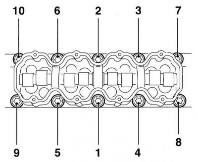
13. Working in the reverse order to that shown, gradually, a quarter turn at a time, loosen the cylinder head mounting bolts enough to allow them to be removed by hand. Remove the bolts from the head complete with their washers.
14. Lift up and separate the timing case from the head; if necessary, tap the case on the sides with a soft-faced hammer.
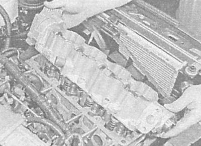
Never pry the housing with a lever to avoid damaging the mating surfaces! Mark the position of the two guide bushings, remove them from the head and put them in a safe place.
15. Separate the cylinder head from the block, - try not to drop the valve drive levers and oil deflector caps. If necessary, lightly tap the sides of the head with a soft-faced hammer - DO NOT PRY it up with a lever under any circumstances (see warning above)! Mark the position of the two guide bushings, remove them and put them in a safe place.
Original article on the web portal: www.OpelBook.ru
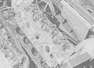
16. Remove the sealing gasket - do not discard the gasket yet in order to identify the new one.
Preparing for installation
1. Thoroughly clean and dry the mating surfaces of the cylinder head and block. Use a hard plastic or wooden scraper to remove all traces of old gasket material and carbon deposits. Also clean the piston crowns. Be extremely careful - the surfaces are easy to damage. Remember that dirt should not get into the oil ducts, water galleries, channels and threaded holes - plug them with plugs or seal them with tape. To prevent carbon deposits from getting into the gaps between the pistons and cylinders, pack the latter with thick grease, which can be easily removed with a stiff brush after the cleaning procedure is complete. After cleaning, wipe all surfaces with a clean, dry rag.
2. Inspect the mating surfaces of the head and block for deep scratches, cracks and other damage. Minor defects can be removed with a fine scraper; in more serious cases, the head should be ground or replaced.
3. Make sure the threaded holes are clean and dry - just in case, blow them out with compressed air (you can use a bicycle pump). The presence of traces of grease in blind holes can lead to the destruction of the block when tightening the bolts as a result of the increase in hydraulic pressure.
4. The head mounting bolts must be replaced without fail, regardless of their current condition.
5. Using a steel ruler and a blade-type feeler gauge, check the flatness of the mating surface of the head (see General and major engine repairs).
6. Replace the cylinder head mounting bolts - the bolts must be replaced without fail, regardless of their current condition.
Installation
1. Bring the piston of the first cylinder to the TDC position at the end of the compression stroke.
2. Using a clean cloth, wipe the mating surfaces of the block and head dry.
3. Make sure both guide bushings are installed in their sockets.
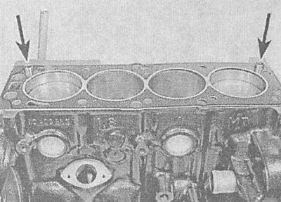
4. Place a new sealing gasket on the mating surface of the cylinder block, with the "OBEN/TOP" marking facing up.
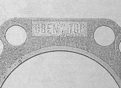
5. Install the head on the cylinder block - make sure that the guide bushings fit correctly into the receiving sockets.
6. Wipe dry the mating surfaces of the head and the camshaft housing with a clean rag. Make sure that the valve drive levers, oil deflector caps and hydraulic compensators are installed correctly.
7. Apply a coat of suitable sealant (consult a service station) on the upper mating surface of the cylinder head.
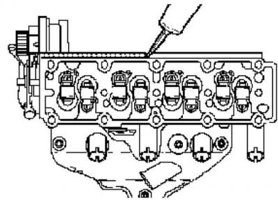
8. Install the guide bushings and lubricate the valve actuator levers with clean engine oil.
9. Carefully install the timing case (with a camshaft embedded in it) on the cylinder head, make sure that the guide bushings fit correctly into the receiving sockets, — make sure that the guide bushings fit correctly into the receiving sockets.
10. Install washers onto the NEW timing case/cylinder head bolts, then install the bolts and tighten them finger tight.
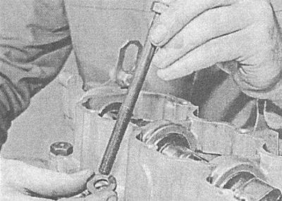
11. Acting in a strictly defined sequence, in several steps evenly, tighten the bolts with the force of the 1st stage.
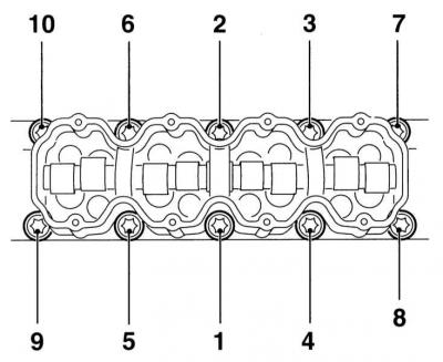
12. In the same order, tighten the bolts to the corners first at stage 2, then at stage 3 and stage 4, using a protractor attachment or using paint or a marker to mark the reference points.
13. Screw in the timing belt rear cover mounting bolts and tighten them to the required torque.
14. Make sure that the right powertrain suspension bracket is installed correctly and tighten its mounting bolts to the required torque.
15. Install the camshaft timing gear (see Removal and installation the timing belt tensioner and timing drive gears) and timing belt (see Removal and installation the timing belt).
16. Restore the original wiring connection, ensure that the harnesses are correctly routed and securely fastened in all the provided intermediate fasteners.
17. Connect the cooling system hoses to the thermostat housing, making sure that the fastening clamps are securely tightened.
18. Install the intake manifold and exhaust manifold (see Chapter Power and exhaust systems).
19. Reinstall the engine guard and right front wheel. Lower the vehicle to the ground and tighten the wheel bolts to the specified torque.
20. Make sure that all hoses are connected correctly and securely, then fill the cooling system (see Chapter Cooling and heating systems).
21. Connect the battery.
22. Start the engine and check it for signs of developing fluid leaks.
Visitor comments