
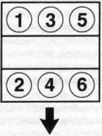
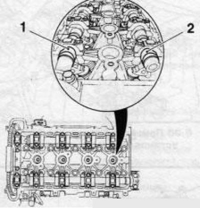
6.1 Numbering of cylinders of a 6-cylinder engine, the arrow indicates the direction of movement of the car
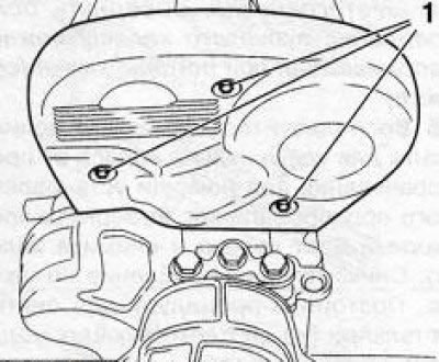
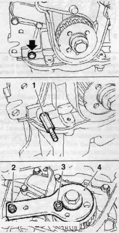
To remove the top cover of the timing drive, loosen the fixing bolts (1) (engines Z16XE/Z18XE)
Note: Cylinder numbers are counted in sequence from 1 to 4. The first cylinder is on the accessory drive/timing side. On 6-cylinder engines, the numbering starts from the nearest left (looking at the engine from the timing side) cylinder (see illustration).
2. Checking and adjusting the valve timing is a very laborious operation and can only be performed using a special tool from Opel, make sure in advance that all the necessary accessories are available and at hand. This tool is usually only available at a service station. In addition, on most engines, this operation requires time-consuming preparatory work - it is recommended to entrust this procedure to Opel company service stations.
Note: Below is a detailed description of the procedure for some engines only. For other engines, the preparatory work is described in Section 8.
3. To bring the piston of the first cylinder to TDC, turn the crankshaft evenly and slowly so that the TDC marks match. Depending on the conditions, cranking the engine crankshaft can be performed in the following ways:
Hang one of the front wheels and put the car on a stand. Engage 5th gear - when turning the suspended wheel, the engine crankshaft will turn (models with manual transmission). Use an assistant to turn the wheel when making adjustments.
If you don't have jacking tools handy, choose a flat, large enough area and engage 5th gear. When moving the car by pushing, the crankshaft will also turn (models with manual transmission).
In stationary conditions, the crankshaft is rotated using a ratchet and a head change, which is installed on the central bolt of the crankshaft pulley, while the neutral gear must be engaged and the parking brake cocked. The crankshaft must be turned clockwise (viewed from the timing side).
Attention! Do not turn the engine by the camshaft gear bolt - this will tighten the toothed belt / timing chain (timing)!
4. Before starting work on setting the TDC, disconnect the wire from the negative terminal of the battery.
Engines Z16XE/Z18XE
5. Remove the engine top cover.
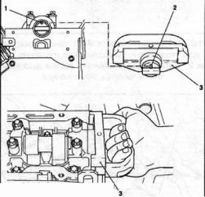
6. Turn out 3 fixing bolts (see resist. illustration), separate the upper timing belt cover from the rear timing case and remove it.
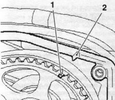
7. Rotate the crankshaft pulley in the direction of engine rotation (clockwise) so that the marks on the pulley and the engine block match (see illustration) - at the same time, the marks on the gear wheels of the camshafts must also match. Now the piston of the first cylinder is at TDC of the compression stroke.
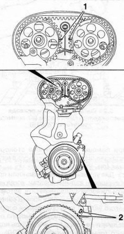
6.7 Setting TDC (engines Z16XE/Z18XE) - labels (2) crankshaft pulley and marks (1) camshaft gears must match
Note: If the camshaft marks are on the outer sides of the gears, turn the crankshaft one more turn.
If the marks of the timing gears do not match, it is necessary to adjust the distribution phases, for which it is necessary to remove the toothed belt
8. After completing the test, reinstall the removed components. Installation is in the reverse order. Before installing the upper timing cover, check its integrity and wipe it thoroughly inside and out.
Engines Z22SE/Z22YH
Attention! Unlike others, these engines determine the TDC of the compression stroke for the piston of the 4th cylinder!
Note: Checking and adjusting the valve timing can only be done using a special tool Opel-KM-6148.
9. Remove the engine cover.
10. Remove the air cleaner and relieve pressure in the fuel supply system.
11. Release from holders, release fastening and remove a fuel line. To prevent dirt from entering the fuel system, close the free ends of the fuel line under the running plugs.
12. Disconnect the crankcase ventilation hose. Close the free end of the hose and the socket with suitable plugs.
13. Remove the ignition module.
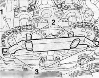
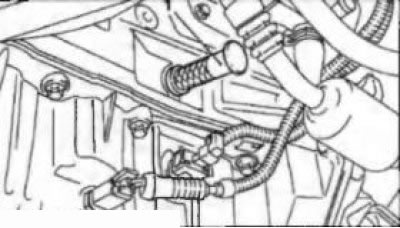
14. Disconnect the cooling system hose, loosen the fixing nut (2) (see illustration) and remove the coolant pipe. Disconnect the 2 connectors of the electrical wiring of the lambda probe and the connector of the valve of the exhaust gas recirculation system (EGR). Turn out 5 bolts and 2 fixing nuts, turn out hairpins and remove the tire «masses». Remove the wiring harness holder.
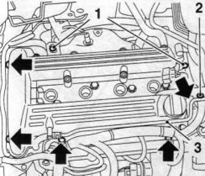
6.14 Preparing the cylinder head cover for removal: 1, 2. Fixing nuts; 3. Coolant tube
15. Turn out 14 fixing bolts and remove a cover of a head of cylinders.
16. Place the car on stands or hang it on a lift.
17. Remove the multirib belt cover.
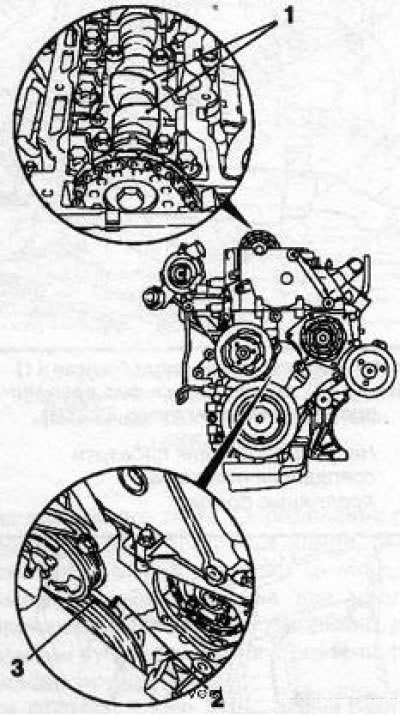
18. Set the TDC of the compression stroke for the piston of the 4th cylinder, for which slowly and evenly turn the crankshaft in the direction of engine rotation until the marks on the crankshaft pulley and on the timing cover match, while the cams cm. resist. illustration) camshafts above the 4th cylinder must be directed upwards.
16.18 When setting the TDC of the compression stroke for the piston of the 4th cylinder, the cams (1 and 2) camshafts must point upwards
Note: If the cams are pointing down when the marks are aligned, rotate the crankshaft 1 more turn.
Lower the car onto its wheels.
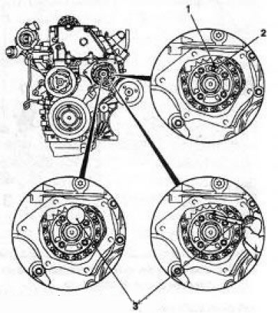
19. To check the valve timing, it is necessary to install a special tool KM-6148 using mounting bolts (see illustration) - in this case, the guides must enter into special holes on the toothed pulleys of the camshafts. If this does not happen, it is necessary to make the appropriate adjustment.
20. Installation of all removed components is made in an order, the return to an order of removal. Before installing the cylinder head cover, clean all mating surfaces and threaded holes, install the cylinder head cover with five new gaskets.
Z19DT engines (H)
Attention! The steering wheel angle sensor setting is lost every time the battery is disconnected and the sensor must be set again after the work is completed!
21. Remove the front right wheel.
22. Remove the bottom cover of the engine compartment.
23. Loosen the crankshaft pulley bolts.
24. Remove the multirib belt.
25. Turn out bolts of fastening of a pulley of a cranked shaft and remove a pulley.
Attachment installation (1) (KM-6148) for checking valve timing (Z22YH engine): 2. Guides for checking the coincidence of holes; 3. Fixing bolts
26. Remove the air cleaner.
27. Remove the right engine mount.
28. Turn out 6 fixing bolts and remove the top cover of a gear belt. Disconnect the wiring from the crankshaft angle sensor. On the Z19DTH engine additionally unscrew the fixing bolt and remove the guide tube of the dipstick for measuring the level of impellent oil and disconnect the line of the crankcase ventilation system (PCV).
29. Z19DT engine - it is necessary to turn the crankshaft until the marks on the camshaft pulley and on the timing case are aligned (see illustration).
Attention! Do not screw on the engine at the camshaft, otherwise the toothed belt will be too tight!
6.29 Queen alignment (1 and 2) camshaft (Z19DT engine)
30. Engine Z19DTH - to check, you must first unscrew the 2 screw plugs at the front and rear on the camshaft housing and screw in special Opel adjusting mandrels instead -EN46789 (from intake valves) And EN-46789-100 (from the exhaust valves) (see illustration). Rotate the crankshaft so that the adjusting mandrels lock into the camshafts.
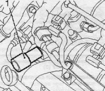
6.30 Installing fixture EN46789 (1) on Z19DTH engine
31. Install tensioner retainer EN-46788 (see illustration), for which unscrew the bolt (arrow) oil pump and replace it with a special mounting pin. Install the retainer on the crankshaft gear and secure it to the gear with a bolt and nut on the mounting stud.
6.31 Fitting the crankshaft lock (4) (EN-46788): 1. Mounting pin; 2. Nut; 3. Fixing bolt
32. If, with the tool installed, the TDC marks on the camshaft pulley and the camshaft housing coincide, then the distribution phases are adjusted correctly. Otherwise remove a gear belt and make appropriate adjustment.
33. At the end of the test, reinstall the removed components. Don't forget to install the engine cover
Y22DTR/Y20DTH engines
Note: During almost the entire period of operation, the timing chain does not require maintenance and adjustment. A description of the preparatory work for checking the valve timing adjustment is given in Section 8.
34. To check the adjustment of the valve timing, the cylinder head cover and the cover of the high-pressure fuel pump drive sprockets must first be removed (injection pump).
35. Slowly and smoothly rotate the crankshaft in the direction of engine rotation (clockwise) until the mark on the crankshaft pulley slightly reaches the mark on the timing cover (si. resist. illustration). The camshaft cams above the first cylinder must be pointing up, otherwise turn the crankshaft one more full turn.
6.35 When aligning marks (2 and 3) cams (1) camshaft above the first cylinder must point upwards
36. Install special tool KM-929 (see illustration) into the hole for installing the crankshaft pulse sensor. Slightly tighten the crankshaft so that the device blocks the shaft from turning - while the marks on the crankshaft pulley and on the timing cover should match.
6.36 Adaptation KM-929 in the established position
37. Check the position of the single chain drive sprocket on the injection pump. The arrow on the sprocket should align with the gap on the flange and the fuel pump mounting hole (see illustration). Install Fixture KM-927 into the mounting hole.
6.37 Installing the KM927 tool (3): 1. Arrow on single timing chain sprocket; 2. Mounting hole
38. Install fixture KM932 on the opposite side of the camshaft so that the pin of the tool enters the hole in the end of the camshaft (see resist. illustration).
6.38 Installing the KM932 tool (3): 1. Hole in the end of the camshaft; 2. Pin
40. If during the installation of the devices any marks do not match or it is not possible to install the devices in the holes intended for them, it is necessary to adjust the timing.
Y30DT and Z32SE engines
41. Engine Z32SE: To check that the timing is correct, the front timing cover must be removed. This operation is described in Section 8, which also describes the procedure for setting the TDC.
42. Engine Y30DT: TDC is set with the top timing cover removed (see Section 8). Gently rotate the crankshaft in the direction of engine rotation (clockwise) until the mark on the next gear (see illustration) The timing will not match the mark on the lower timing case cover. In this case, the marks on the crankshaft pulley and on the case of the lower timing cover must match, and the marks on the camshaft bosses with the marks on the drive gears of the camshafts - on the shaft of 2-4-6 cylinders with a mark «LH», and on the shaft there are 1-3-5 cylinders with a mark «RH».
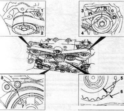
6.42 Marks for setting the TDC of the compression stroke for the 1st cylinder (Y30DT engine): 1, 3. On the camshaft covers; 2, 4. On the gear wheels of the camshaft drive; 5. On the driving gear; 6, 8. On the bottom cover; 7. On the crankshaft pulley
Note: An inspection mirror may be required to check marks. If at least one pair of marks does not match, it is necessary to remove the toothed belt and adjust the timing drive.
Visitor comments