
General information
1. Top dead center (TDC) is the highest point of the piston stroke in its cylinder. In 4-stroke engines, during the rotation of the crankshaft, this position is reached by each of the pistons twice during one working cycle: once at the end of the compression stroke and the second at the end of the exhaust stroke. Determining the TDC position of the piston at the end of the compression stroke (usually the first cylinder) is essential for many subsequent work, such as replacing the toothed belt, checking the valve timing and replacing the cylinder head gasket. Sometimes the TDC of the compression stroke is also called the ignition timing.
Note: Cylinder numbers are counted from 1 to 4. The first cylinder is on the accessory/timing side.
2. This section most fully describes the procedure for setting the TDC of the first cylinder of the 1.6L Z16XEP engine. For other engines, only the features of setting the TDC are given. When carrying out the work, some special tools and devices from Opel will be required, make sure in advance that all the necessary accessories are available and at hand.
3. To bring the piston of the first cylinder to TDC, turn the crankshaft evenly and slowly so that the TDC marks match. Depending on the conditions, cranking the engine crankshaft can be performed in the following ways:
- Hang and place on stands the front of the car. Engage 5th gear - when turning one of the suspended wheels, the engine crankshaft will turn (models with manual transmission). Use an assistant to turn the wheel when making adjustments.
- If you don't have jacking tools handy, choose a flat, large enough area and engage 5th gear. When moving the car by pushing, the crankshaft will also turn (models with manual transmission).
- In stationary conditions, the crankshaft is rotated using a ratchet and a head change, which is installed on the central bolt of the crankshaft pulley, while the neutral gear must be engaged and the parking brake cocked. The crankshaft must be turned clockwise (viewed from the timing side).
Attention: Do not turn the engine by the camshaft gear bolt - this will tighten the toothed belt / timing chain (timing)!
Z16XEP engine
4. Remove the air cleaner (see chapter 4).
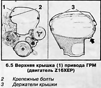
5. Remove the top toothed belt/timing cover (see resist. illustration), to do this, loosen the 2 fixing bolts, disconnect the drive cover from the casing and then slightly pull it on the lug (arrow) up.
6. Remove the right engine boot (see Section 5).
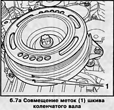
7. Rotate the crankshaft pulley in the direction of engine rotation (clockwise) so that the marks on the pulley and the casing match (see resist. illustration 6.7a) - while the marks on the gears of the camshafts (see resist. illustration 6.7b) should be opposite each other. Now the piston of the first cylinder is at TDC of the compression stroke.
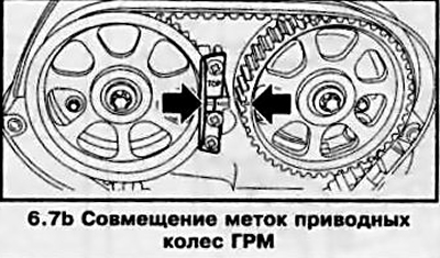
Note: If the marks are on the outer sides of the timing wheels. turn the crankshaft one more turn.
If the timing pulley marks do not match, it is necessary to adjust the distribution phases, for which remove the toothed belt (see Section 8) - it is recommended to contact the service station of the Opel campaign.
8. After completing the test, reinstall the removed components. Installation is in the reverse order. Before installing the upper timing cover, check its integrity and wipe it thoroughly inside and out.
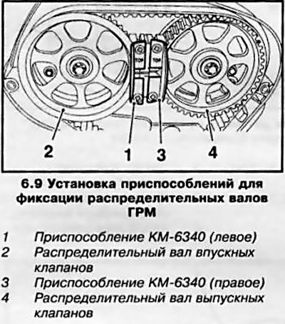
9. If, in addition to checking the valve timing, setting the TDC is required for other work on the engine, you must first disconnect the negative battery cable and, after removing the top cover of the toothed belt, remove the multirib drive belt (see Section 7), and fix the gears of the camshafts with special devices (see resist. illustration).
Z18XE engine
10. Remove the engine top cover (see section 2).
11. Remove the air cleaner (see chapter 4).
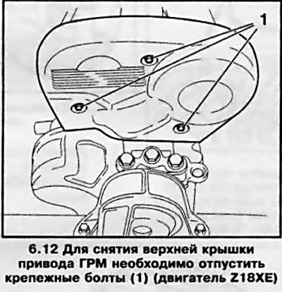
12. Remove the top timing belt cover (see resist. illustration), for which release 3 fixing bolts.
13. Turn the crankshaft pulley in the direction of engine rotation (clockwise) so that the marks on the pulley and the engine block match (see resist. illustration) - at the same time, the marks on the gears of the camshafts must also match. Now the piston of the first cylinder is at TDC of the compression stroke. At the Opel service station, for a more accurate determination of the TDC position, a KM-852 fixture is installed between the gears of the camshafts.
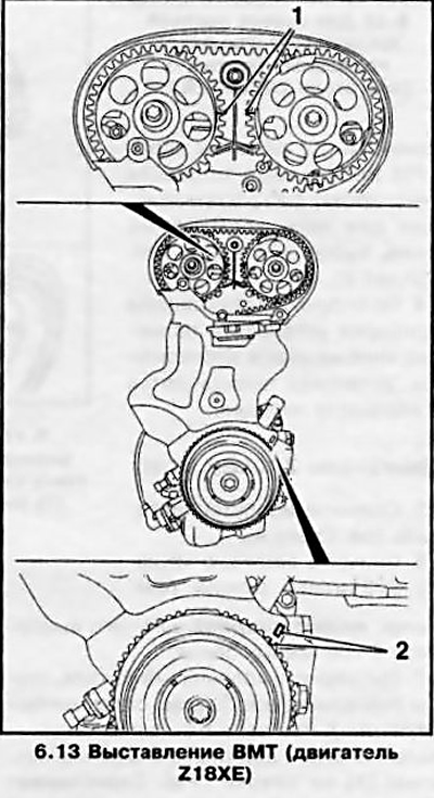
Note: If the camshaft marks are on the outer sides of the gears, turn the crankshaft one more turn.
If the timing gear marks do not match, it is necessary to adjust the distribution phases, for which it is necessary to remove the toothed belt (see Section 8).
14. At the end of the test, reinstall the removed components. Installation is in the reverse order.
Z20LE engines (L/R/H)
15. Remove the air cleaner (see chapter 4).
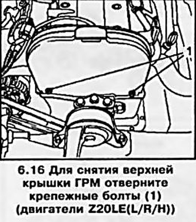
16. Remove the top timing belt cover (see resist. illustration), for which unscrew the 2 fixing bolts.
17. Turn a cranked shaft so. to match labels (2) (see resist. illustration), while the marks of the camshafts must match the marks (1) on the timing case.
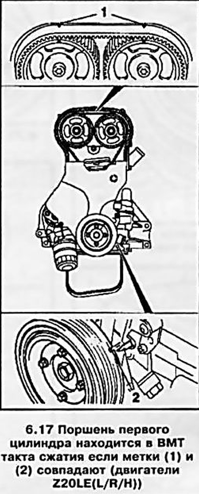
Note: If the camshaft marks are on the outer sides of the gears, turn the crankshaft one more turn.
If the camshaft marks do not match, the valve timing is adjusted, for which it is necessary to remove the toothed belt (see Section 8).
18. At the end of the check, reinstall all removed components.
Z14XEP engine
19. Checking and adjusting the valve timing is a very time-consuming operation and can only be performed using a special tool from Opel KM-952, KM-953 and KM-954.
Examination
20. Remove the air cleaner (see chapter 4).
21. Remove the ignition module (see Chapter 1, Section 22)
22. Disconnect sensors and wiring (see resist. illustration) from the cylinder head cover.
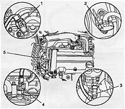
6.22 Disconnecting the sensors from the cylinder head cover (Z14XEP engine)
1 Camshaft sensor
2 Air flow sensor
3 Engine oil pressure sensor
4 Coolant temperature sensor
5 Wiring box
23. Disconnect 2 hoses of the crankcase ventilation system.
24. Turn out 13 bolts of fastening and remove a cover of a head of the block of cylinders, remove the remains of an old laying of a cover and clear interfaced surfaces.
25. Remove the right engine boot (see Section 5).
26. Turn out a bolt closing an adjusting opening of a cranked shaft (see resist. illustration) and lower the car.
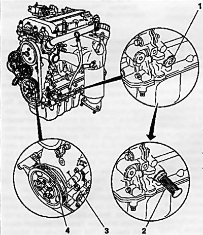
6.26 Setting TDC on the Z14XEP engine
1 Crankshaft adjusting hole bolt
2 Installed fixture KM-952
3 Mark on the timing cover
4 Mark on the crankshaft pulley
27. Install the KM-952 tool in the hole (see illustration 6.26), and slowly and smoothly turn the crankshaft until the tool engages with the crankshaft (will fix the shaft) - at the same time, the marks on the crankshaft pulley and on the timing cover should match, with the timing cams above the first cylinder (see resist. illustration) should look in opposite directions from the middle of the engine - if this position is not observed, turn the crankshaft 1 more revolution.
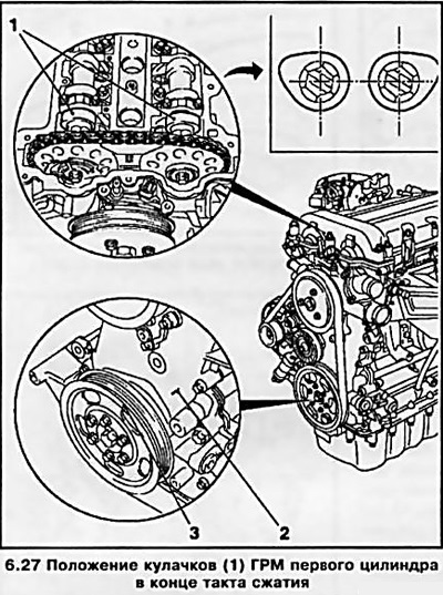
28. Install in the grooves of the camshafts (flywheel side) special device KM-953 (see resist. illustration) - the protrusions of the fixture should enter the grooves to the greatest possible depth. If it is not possible to install the device, it is necessary to adjust the valve timing (see below).
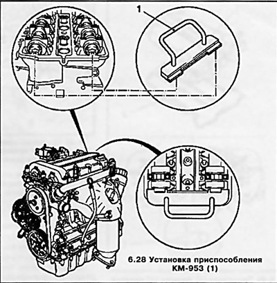
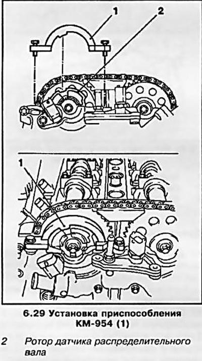
29. Install special tool KM-954 (see resist. illustration) so that the protrusion of the tool falls into the notch of the rotor of the camshaft sensor. If the protrusion and recess do not match, adjust the valve timing (see below).
Adjustment
30. Unlike models with a timing belt drive, the valve timing on this engine can be adjusted without removing the drive cover and the chain itself.
31. At the end of the check, remove the KM-953 and 954 fixtures from the engine.
Caution: Under no circumstances should control devices be used to keep the motor shafts from turning!
32. Turn out a bolt, having released a hole for installation of adaptation KM-955-1 (see illustration 6.32a). Using an open-end wrench, press the intake camshaft in the direction indicated by the arrow and fix the chain tensioner with KM-955-1, thereby loosening the chain tension.
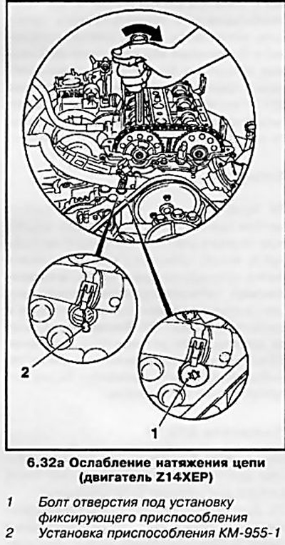
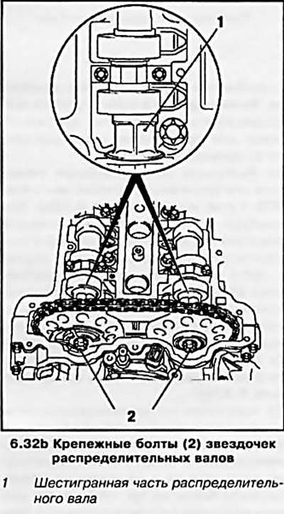
Attention: When pressing/turning the camshafts, the key must only be installed on the hexagonal part of the shaft (see illustration 6.32b)!
33. While holding the camshafts from turning, loosen the fastening bolts of the sprockets of both shafts (see illustration 6.32b), and then unscrew them one by one and replace them with new ones. Tighten the bolts, notes to the intake camshaft sensor rotor (see illustration 6.29) could be turned by hand.
34. Install the KM-953 tool by turning the camshafts with an open end wrench and remove the KM-955-1 tool.
35. Install the KM-954 fixture so that the protrusion of the fixture coincides with the notch of the rotor (see illustration 6.29) - If necessary, tighten the rotor manually.
36. Screw in place the bolt of the hole for installing the KM-955-1 fixture and tighten with the required force. Tighten the mounting bolts of the camshaft sprockets with a force of 10 Nm - no more, then remove all adjusting devices.
37. Tighten the fastening bolts of the sprockets with a force of 50 Nm and another 60°- if necessary, use the help of an assistant, then smoothly turn the engine crankshaft 2 full turns and use the tools to check the TDC position - if the tools are not installed (see above), re-adjust the valve timing.
Installation
38. Installation of all removed components is made in an order, the return to an order of removal. When reassembling, use a new cylinder head cover gasket (see resist. illustration), apply sealant (gray color) at the joints of the cylinder head and timing cover.
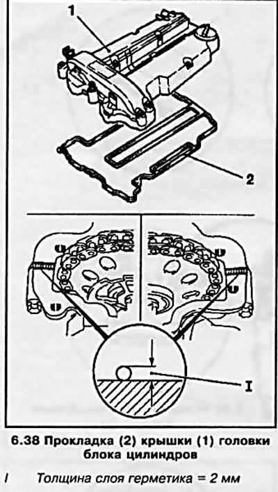
Attention: The cover must be installed within 10 minutes after applying the sealant!
Don't forget to replace the adjusting hole bolt gasket.
Z22YH engine
Attention: Unlike others, this engine determines the TDC of the compression stroke for the piston of the 4th cylinder!
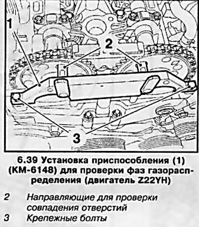
39. To check the valve timing after carrying out the preparatory work and turning the crankshaft pulley until the marks are aligned, it is necessary to install a special tool KM-6148 using the mounting bolts (see resist. illustration) - in this case, the guides must enter the special holes on the toothed pulleys of the camshafts. If this does not happen, it is necessary to make the appropriate adjustment.
Z19DT engine (H)
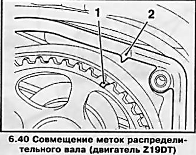
40. Engine Z19DT - it is necessary to turn the crankshaft until the marks on the camshaft pulley and on the timing case are aligned (see resist. illustration).
41. Z19DTH engine - to check, you must first unscrew 2 screw plugs in front and behind on the camshaft housing and screw in special adjusting mandrels Opel-EN-46789 instead (from intake valves) and EN-46789-100 (from the exhaust valves). Rotate the crankshaft so that the adjusting mandrels lock into the camshafts.
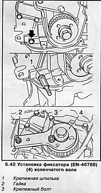
42. Install EN-46788 crankshaft retainer (see resist. illustration), for which unscrew the bolt (arrow) oil pump and replace it with a special mounting pin. Install the retainer on the crankshaft gear and secure it to the gear with a bolt and nut on the mounting stud.
43. If, with the tool installed, the TDC marks on the camshaft pulley and the camshaft housing coincide, then the distribution phases are adjusted correctly. Otherwise, remove the toothed belt and make the appropriate adjustment - this operation is recommended to be entrusted to the specialists of the service station.
44. At the end of the test, reinstall the removed components. Don't forget to install the engine cover (see section 2).
Z17DT engine (L/H)
45. Remove the engine cover (see section 2).
46. Remove the air cleaner (see chapter 4).
47. Remove the wiring box bolt from the top front timing cover (see resist. illustration), disconnect the wiring harness and vacuum tube.
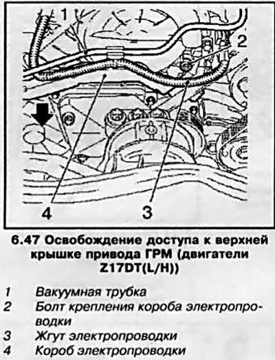
48. Disconnect the vacuum tube (see resist. illustration) from the timing cover (3 holders), remove the 8 fixing bolts and remove the drive top cover.
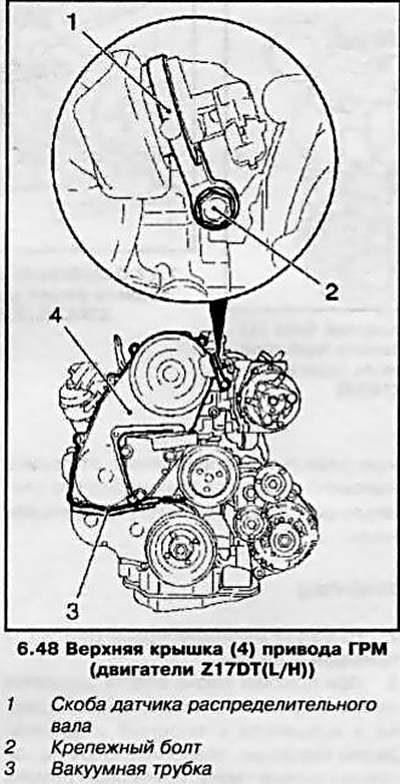
Attention: Bolts of various lengths are used to fasten the upper cover of the toothed belt - remember the installation position of the bolts!
49. Remove the camshaft sensor bracket (see illustration 6.48).
50. Turn the crankshaft until the holes on the gears of the camshaft and high pressure fuel pump are aligned with the holes on the engine housing and screw in the set bolts (see resist. illustration) M6 in the corresponding hole of the camshaft wheel and M8 in the injection pump drive wheel.
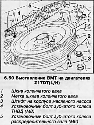
51. Remove the crankcase protection (see Section 5) and check the alignment of the marks - with the set bolts screwed in, the mark on the crankshaft pulley should match the pin on the oil pump cover.
Note: With the crankshaft pulley removed, the mark on the drive gear should line up with the boss on the oil pump cover.
If the labels do not match, it is necessary to adjust the distribution phases (see Section 8) - First remove the toothed belt.
52. At the end of the check, reinstall all the removed components.
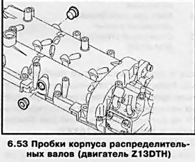
Z13DTH engine
53. Remove 2 plugs from the camshaft housing (see resist. illustration). Clean the threads and screw the fixing pins into the holes (Opel-EN-46781) - upon completion of the installation, the flats on the outer side of the studs should be horizontal. Mark the studs if necessary.
54. Rotate the crankshaft clockwise until the spring-loaded locking pins lock into place.
Attention: When turning the crankshaft, the assistant must ensure that the fixing pins do not turn!
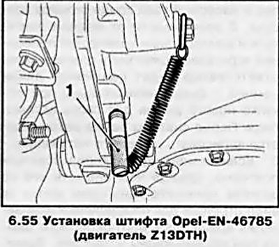
55. Insert the Opel-EN-46785 pin into the special hole on the manual transmission (see resist. illustration), while rotating the crankshaft slightly back and forth to fit the pin into the hole in the flywheel. If the pin does not fit into the flywheel, the valve timing must be adjusted.
Visitor comments