
Gasoline engines
Withdrawal
1. On models with a timing belt drive, to remove the camshafts, you must first remove the toothed belt (see Section 8). Before loosening the toothed belt, move the engine off TDC by turning the crankshaft 60°counterclockwise so that neither piston is at TDC.
2. Remove the camshaft gears (see Section 5).
Note: The removal of the Z14XEP engine sprockets is described below.
3. Remove the cylinder head cover, for which first remove the ignition module (see Chapter 1, Section 22).
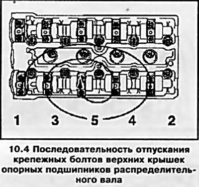
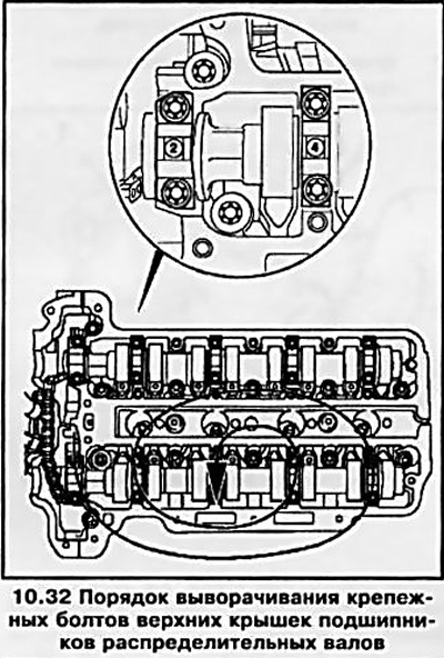
4. First of all, the exhaust camshaft is removed: moving in a spiral from the edges inward (in the sequence shown in Fig. illustrations), in several steps, 1-0.5 turns per approach, evenly loosen the bolts securing the upper shaft covers, then completely unscrew the bolts.
5. When removing the upper covers of the camshafts, pay special attention to the numbering of the covers - during assembly, they must be installed strictly in their original places. If for any reason there are no marks, they must be applied independently using a marker.
Attention: Failure to be careful when loosening the fasteners of the thrust bearing caps can lead to their mechanical damage; if handled carelessly, the camshaft bearings can be damaged. If at least one cover is broken, you will have to change the entire head of the block - in the manufacture of covers, they are processed together with the head and are not supplied to the spare parts market individually!
6. Lift the camshaft and remove it from the engine, carefully remove the oil seal (timing belt models).
7. Acting in a similar manner, remove the inlet camshaft - during installation, the shafts must be installed only in their places.
8. Prepare 16 small clear plastic bags or clean plastic cups and label them according to the valve numbers. Using the tools, remove the pushers from the head and place them in the appropriate cups.
Note: To prevent oil leakage from the hydraulic tappets (with appropriate equipment) lay the pushers with the working ends up.
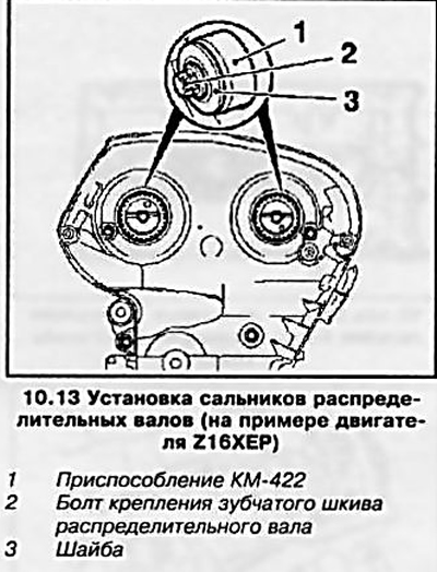
Examination
9. Wipe the timing parts with a clean rag and carefully examine the condition of the bearing journals and camshaft cams. In case of scoring, scratches or signs of wear of the camshafts, they must be replaced together with the hydraulic pushers. If the thrust bearings are worn or damaged, the cylinder head assembly must be replaced (see paragraph 5).
10. Alternately laying the camshafts in prisms, using a plunger-type dial gauge, determine the amount of their radial runout (on bearing journals). If the measurement results are out of range, the camshaft must be replaced.
11. Check up a condition of pushers and their landing sockets in a head. If there are signs of excessive wear of the working surfaces, cracks, scoring and other damage, replace the pushers. Note: The tappets must also be replaced if the operation of the valve mechanism has recently been accompanied by an increased background noise.
Installation
12. Before installation, lubricate the mating surfaces of the camshafts with molybdenum-containing grease (with MoS2 content). Install the intake valve shaft first and tighten the mounting bolts in the reverse order of loosening (see illustration 10.4), then install the exhaust valve shaft.
13. Press in new oil seals using the KM-422 tool (see resist. illustration) or other suitable tool. Before installation, lubricate the outer surfaces of the oil seals with silicone grease (white color). Install the cylinder head covers.
14. Install the camshaft gears (see Section 5).
15. Adjust the valve timing and install the toothed belt (with appropriate equipment) (see Section 8). Reinstall all removed components.
Features for Z16XEP engine
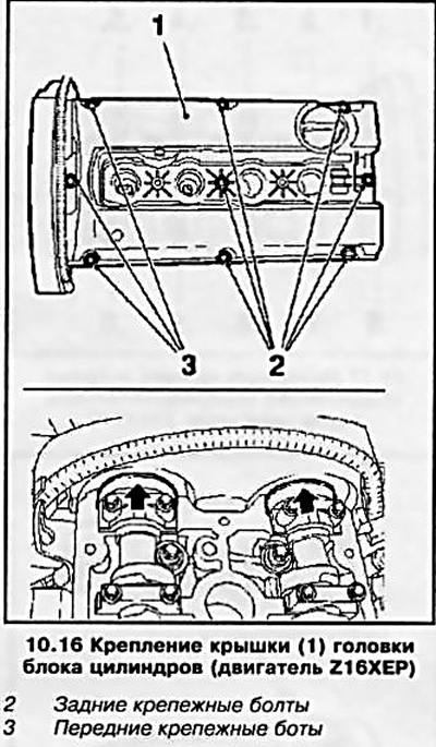
16. Before removing the cylinder head cover, it is necessary to disconnect all electrical wiring connectors and hoses of the crankcase ventilation system. Then unscrew the 3 front mounting bolts (see resist. illustration), pull them up and fix them to the lid with adhesive tape. Remove the 6 remaining mounting bolts and remove the cover. Make sure the front bearing caps are (shown by arrows) there are no traces of sealant left - wipe them with a clean rag.
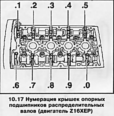
17. The numbering of the camshaft bearing caps is shown in Ref. illustrations.
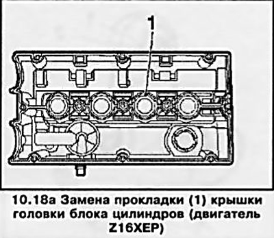
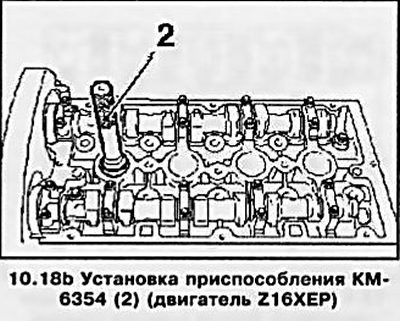
18. Install a new gasket (see resist. illustration 10.18a) into the cylinder head cover, remove the spark plug (see Chapter 1, Section 22) of the first cylinder and screw the KM-6354 tool into its place (see resist. illustration 10.18b).
19. Carefully, so that the gasket does not fall out, install the head cover (see resist. illustration): Back side first, then gently press the front side of the cover.
Attention: If the gasket is not seated evenly when installing the cover, the engine may subsequently fail! Take out the fixture.
20. Remove adhesive tape and tighten all cover mounting bolts. Screw in the spark plug of the first cylinder.
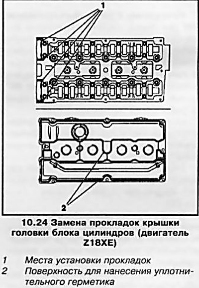
Features for Z18XE engine
21. Before removing the cylinder head cover, disconnect all wiring connectors and hoses. Turn out fixing bolts and remove a cover.
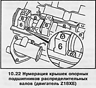
22. The numbering of the camshaft bearing caps is shown in Ref. illustrations.
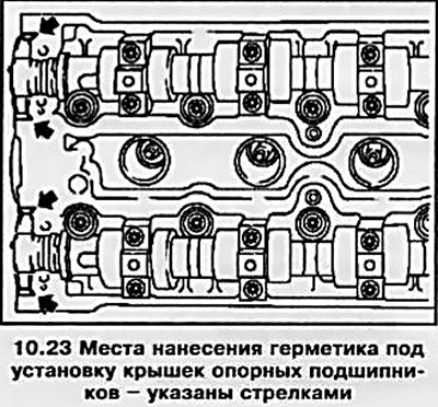
23. Before installing the camshaft bearing caps, clean the mating surfaces of the guides (front) bearings (see resist. illustration), apply fresh sealant (Green colour) and install covers.
24. Before installing the cylinder head cover, clean all mating surfaces, replace the gaskets on the cylinder head cover (see resist. illustration) and apply fresh sealant (black color). Establish a cover on a head of cylinders and tighten fixing bolts with the demanded effort.
Features for Z20LE engines (L/R/H)
25. Before removal of a cover of a head of cylinders it is necessary to disconnect all bringing sockets of electroconducting and hoses. Turn out fixing bolts and remove a cover.
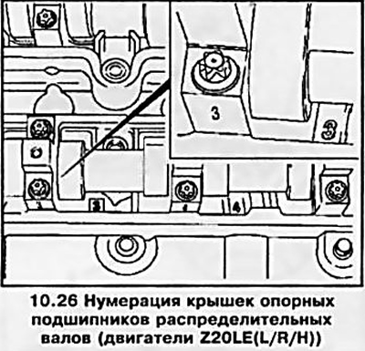
26. The numbering of the camshaft bearing caps is shown in Ref. illustrations.
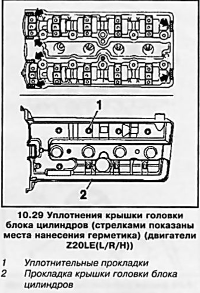
27. Before installing the camshaft bearing caps, clean the mating surfaces of the guides (front) bearings (see illustration 10.23), apply fresh sealant (Green colour) and install covers.
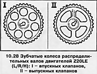
28. Camshaft gears are different from each other (see resist. illustration), reinstall them with the adjustment marks facing out.
29. Apply sealant (black color) at the joints, replace the gaskets on the cylinder head cover (see resist. illustration). Install the cover and tighten the fixing bolts to the required torque.
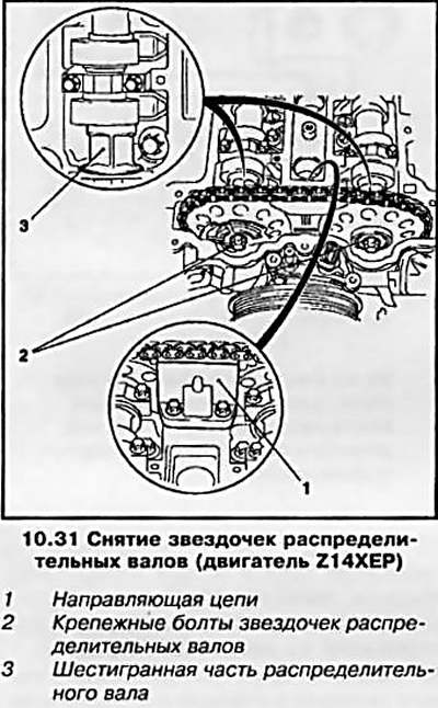
Features for Z14XEP engine
30. Set the piston of the first cylinder to the TDC position and loosen the timing chain by pulling the chain tensioner and fixing it with the tool (see Section 6).
Note: If the timing cover has not been removed, to install the KM-955-1 tool, you must first unscrew the chain tensioner cover.
31. Having unscrewed 2 fixing bolts, remove the guide (see resist. illustration) timing chains. Holding the camshafts from turning with an open-end wrench by the hexagonal part of the shaft, unscrew the fixing bolts and remove the camshaft sprockets.
32. Please note - all upper camshaft bearing caps have their own number (see resist. illustration): 1, 3, 5, 7, 9 - exhaust valve shaft and 2, 4, 6, 8, 10 - intake valve shaft. Unscrew the fixing bolts of the exhaust camshaft support bearing caps, remove the caps and remove the shaft. Then remove the intake camshaft.
33. Before installation, lubricate the mating surfaces of the camshafts and hydraulic pushers with molybdenum grease (with MoS content2). Install the intake valve shaft first and tighten the mounting bolts in the reverse order of loosening, then install the exhaust valve shaft.
Attention: When installing the shafts, the piston of the first cylinder must be at TDC.
34. Install the camshaft sprockets and secure them with new bolts, adjust the valve timing and reinstall all the removed components (see Section 6).
Diesel engines
Z17DT engines (L/H)
Withdrawal
35. Disconnect the battery (see chapter 5) and remove the fuel injection nozzles (see chapter 4).
36. Remove the toothed belt (see Section 8).
37. Rotate the engine 60°counterclockwise and remove the camshaft sprocket (see Section 5).
Note: The wheel is mounted on the intake camshaft and drives the exhaust camshaft through a gear train.
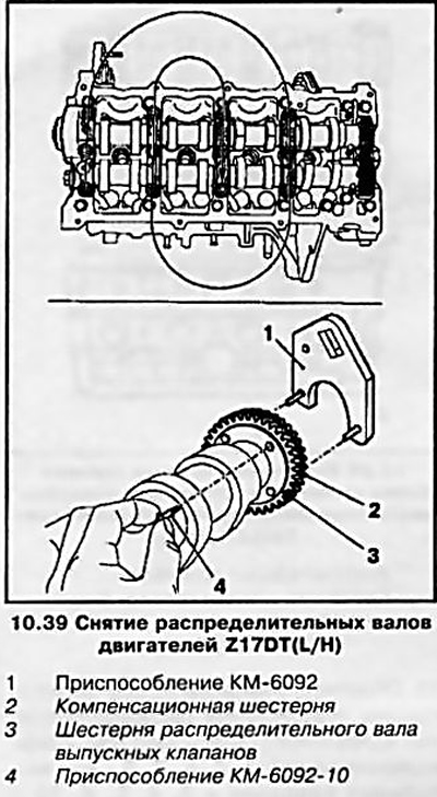
38. Block the exhaust camshaft together with the compensation gear from turning (see resist. illustration), for which remove the support bearing cover closest to the shaft gears and install the KM-6092-10 tool.
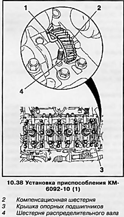
39. Moving in a spiral from the edges inward (in the sequence shown in Fig. illustrations), in several steps, 1-0.5 turns per approach, evenly loosen the bolts securing the upper shaft bearing caps, then completely unscrew the bolts. Before removing the covers, mark them so that they can be reinstalled in the same place later. Carefully remove the shafts - when removing the exhaust valve shaft, in addition to the KM-6092-10 tool, install the KM-6092 tool to securely fix the compensation gear on the camshaft gear (see ibid).
40. Carefully, so as not to damage the seating surfaces, remove the intake camshaft oil seal (see resist. illustration).
Examination
41. The procedure for checking timing components is the same as for gasoline models (see above).
Installation
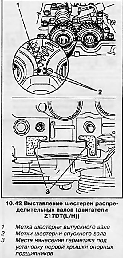
42. Lubricate the mating surfaces of the shafts with clean engine oil. Before installing the shafts, engage their gears and install the shafts on the engine so that the exhaust shaft gear mark is between the intake shaft marks (see resist. illustration), while the marks should be approximately at the level of the upper edge of the camshaft housing. Apply sealant (Green colour) for sealing the joint of the first support bearing cover.
43. Replace the four front covers and hand-tighten the bolts and nuts to secure them.
Note: The arrows on the bearing caps must point towards the timing drive. Remove tool KM-6092-10 and install the fifth support bearing cover.
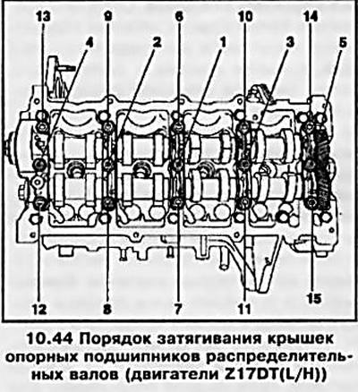
44. Tighten with the required force 10 fixing nuts and 5 nuts in several stages, making one at a time - half a turn per approach in the order of the numbering shown on Ref. illustrations.
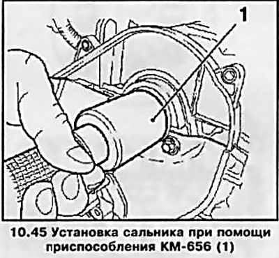
45. Lubricate the outer surface of the new camshaft oil seal and install it using tool KM-656 (see resist. illustration).
46. Install the camshaft gear (see Section 5), adjust the valve timing (see Section 6), install the toothed belt (see Section 8) and check and adjust the valve clearances (see Section 9). The rest of the removed components are installed in the reverse order of removal (see relevant sections and chapters).
Removal / installation of the timing case (on the example of an engine with an A/C compressor drive)
47. A design feature of the timing of this engine is that the support bearings are made on a separate timing case. If necessary, they can be replaced without changing the cylinder head.
48. On models with an A/C system, before performing work, it is necessary to remove the refrigerant from the system using special service equipment (contact the service station of the Opel campaign) and drain the coolant (see chapter 3).
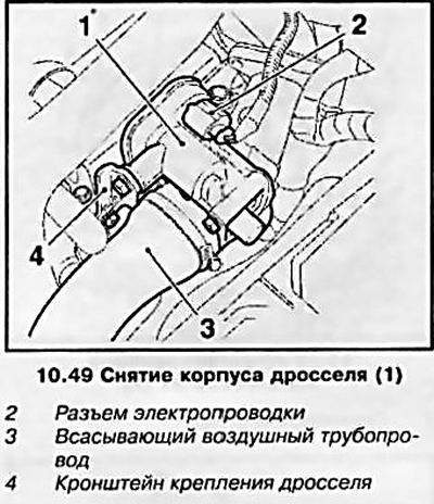
49. When removing attachments, in addition to removing the injectors (see chapter 4) it is necessary to remove the throttle body, disconnecting all supply lines from it (see resist. illustration).
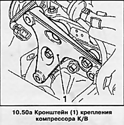
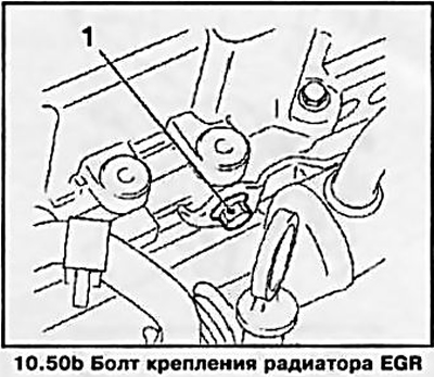
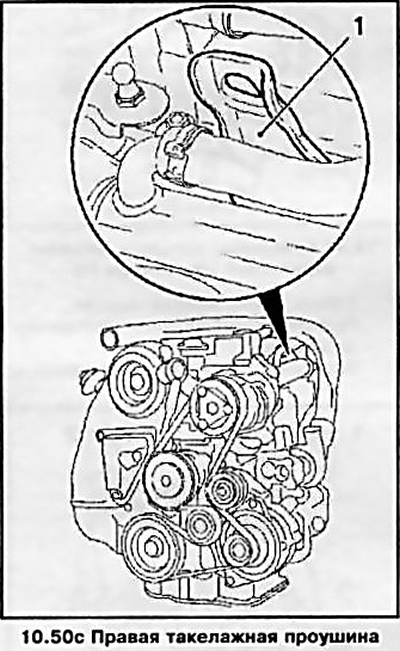
50. Before removing the m injectors, it is necessary to disconnect the cooling system pipelines, the electrical connector from the A/C compressor, unscrew the 3 mounting bolts and remove the compressor, and then the compressor mounting bracket, EGR radiator and the right lifting eye (see resist. illustrations).
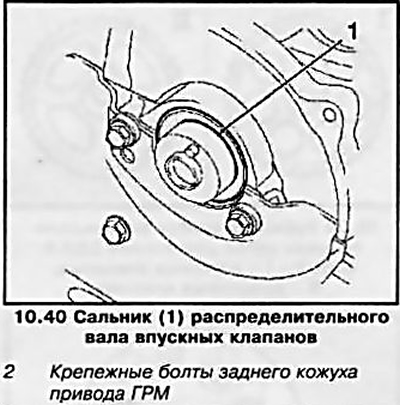
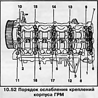
51. After removing the gears (see Section 5) disconnect the rear timing cover (see illustration 10.40), by unscrewing the 2 fixing screws.
52. Turn out 17 fastening elements of the timing case in order from 1 to 17 (see resist. illustration) in several steps, releasing each element 1-0.5 turns per approach, and remove the housing from the engine.
53. Installation, including tightening the timing case, is carried out in the reverse order of removal - do not forget to replace the gasket under the timing case.
Visitor comments