OpelBook.ru
Cars AvtoVAZ Cars Mitsubishi Cars BMW Cars Mercedes Cars Nissan Cars Toyota Cars Chevrolet
English Русский
Български
Беларускі
Український
Српски
Hrvatski
Română
Polski
Slovenský
Magyar
 |  Sitemap  |  Contacts  |    


Main Astra Corsa Insignia Kadett Omega Vectra Zafira Others Articles
Astra F (1991-1998, petrol) Astra G (1998-2004, petrol) Astra G (1998-2004) Astra H (2004-2009) Astra J (2009-2015, petrol)
  • Main
  • Astra
  • Astra H
  • Power unit
  • Engine repair
  • Removal and installation the oil pan

Removal and installation the oil pan (Opel Astra H)

            0

Contents: Z16XEP Engine ⬇ Z18XE Engine ⬇ Engines Z20LE(L/R/H) ⬇ Z14XEP Engine ⬇ Z17DTL/H Engines ⬇

Z16XEP Engine


1. Remove the engine oil dipstick, unscrew the mounting bolt of the lifting eye and remove the eye, remove the engine oil dipstick tube.

2. Raise the car on a lift and remove the right engine boot (see Section 5).

3. Disconnect the lambda probe cable channels (see illustration 11.6).

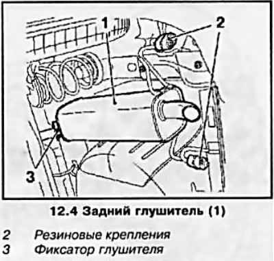
4. Loosen the rear muffler retainer, release the muffler from the two holders and, with the help of an assistant, remove it (see accompanying illustration).

4. Loosen the rear muffler retainer, release the muffler from the two holders and, with the help of…


5. Disconnect the exhaust pipe from the catalytic converter (see illustration 11.7).

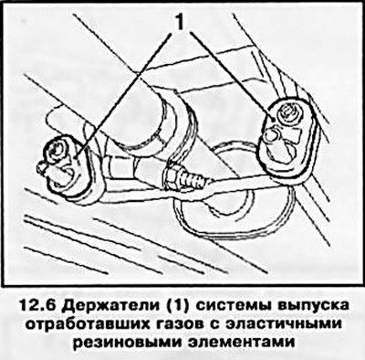
6. Remove the exhaust pipe by disconnecting it from the front muffler (see accompanying illustration).

6. Remove the exhaust pipe by disconnecting it from the front muffler (see accompanying…


7. Drain the engine oil from the engine crankcase (see Chapter 1, Section 6) and disconnect the engine oil level sensor wiring connector.


8. Remove 2 rubber plugs, unscrew 3 bolts securing the oil pan to the transmission, and then 15 bolts securing the oil pan (see accompanying illustration) and, using a suitable tool, pry and disconnect the oil pan.
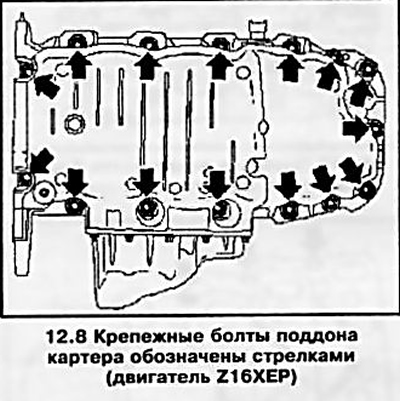
8. Remove 2 rubber plugs, unscrew 3 bolts securing the oil pan to the transmission, and then 15…


9. Before installing the tray, clean all mating surfaces from any remaining sealant and pre-tap the threads of 15 holes.

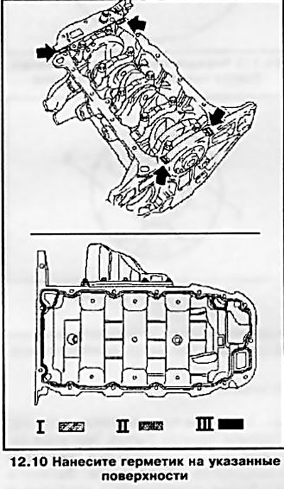
10. Apply a bead of sealant (gray color) 2-3 mm thick on the surfaces indicated in the accompanying illustration, and install the tray in place.

10. Apply a bead of sealant (gray color) 2-3 mm thick on the surfaces indicated in the accompanying…


Note: Installation must be completed no later than 10 minutes after applying the sealant.


11. Installation of the remaining components is carried out in the reverse order of their removal.

Z18XE Engine


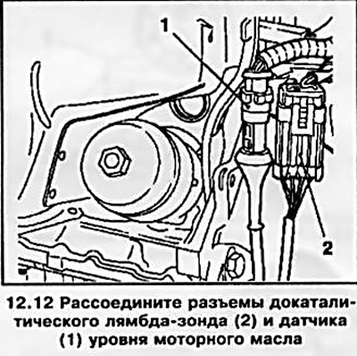
12. Disconnect the electrical wiring connectors of the pre-catalytic lambda probe and engine oil level sensor (see accompanying illustration).


12. Disconnect the electrical wiring connectors of the pre-catalytic lambda probe and engine oil…


13. Raise the car on a lift, remove the exhaust system (see Chapter 4).

14. Drain the engine oil from the engine crankcase (see Chapter 1, Section 6). Before screwing in the drain plug, do not forget to replace the gasket.

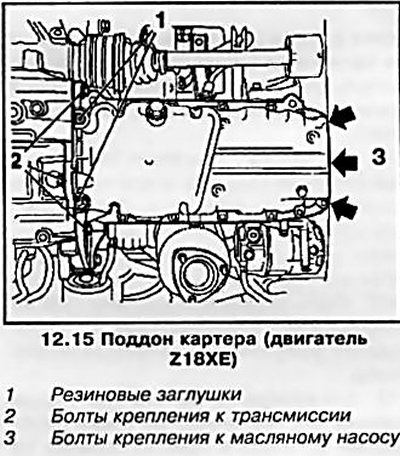
15. Remove the 2 rubber plugs and the mounting bolts shown in the accompanying illustration and the 12 oil pan mounting bolts. Using a suitable tool, pry the oil pan off.

15. Remove the 2 rubber plugs and the mounting bolts shown in the accompanying illustration and the…


16. Before installing the tray, clean all mating surfaces from any remaining sealant and pre-thread all holes.

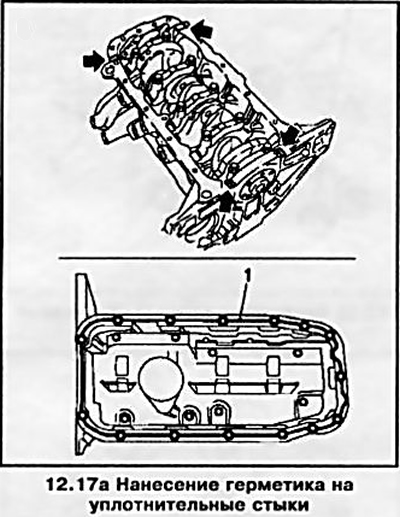
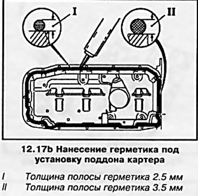
17. Apply a bead of sealant (gray color) 2.5-3.5 mm thick on the surfaces indicated in the accompanying illustrations and install the tray in place.

17. Apply a bead of sealant (gray color) 2.5-3.5 mm thick on the surfaces indicated in the…


17. Apply a bead of sealant (gray color) 2.5-3.5 mm thick on the surfaces indicated in the…


Attention: Installation must be completed no later than 10 minutes after applying the sealant.


18. Installation of the remaining components is carried out in the reverse order of their removal.

Engines Z20LE(L/R/H)


19. Remove the crankcase guard (see Section 5) and disconnect the catalytic converter lambda probe wiring connector.

20 Remove the front exhaust pipe and drain the engine oil from the engine crankcase (see Chapter 1, Section 6).

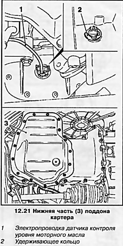
21. Disconnect the engine oil level sensor wiring and remove the retaining ring, then unscrew the mounting bolts of the lower part of the oil pan and remove it (see accompanying illustration).

21. Disconnect the engine oil level sensor wiring and remove the retaining ring, then unscrew the…


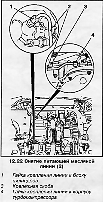
22. Loosen the nuts and remove the turbocharger oil feed line (see accompanying illustration).

22. Loosen the nuts and remove the turbocharger oil feed line (see accompanying illustration).


23. Using the KM-726-A tool, remove the oil pump oil filter.

24. Remove the bolts securing the top of the pan to the transmission assembly (see accompanying illustration), separate the pan from the engine block and remove the oil pump (see Section 13).
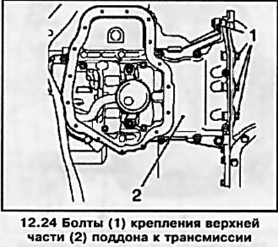


24. Remove the bolts securing the top of the pan to the transmission assembly (see accompanying…


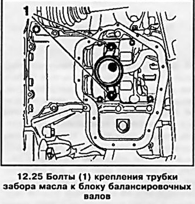
25. Disconnect the oil pickup tube from the balance shaft block (see accompanying illustration).

25. Disconnect the oil pickup tube from the balance shaft block (see accompanying illustration).


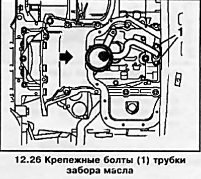
26. Move the upper part of the pan in the direction indicated by the arrow in the accompanying illustration, unscrew the 2 mounting bolts and remove the upper part of the oil pan together with the oil pick-up tube.

26. Move the upper part of the pan in the direction indicated by the arrow in the accompanying…


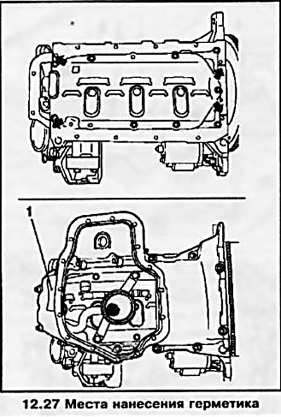
27. Before installing the pan, clean all mating surfaces from sealant residues and old gaskets. Install all removed components in the reverse order of their removal, do not forget to replace all gaskets. Apply sealant before installing the upper part of the oil pan (black color) at the indicated points (see accompanying illustration) and lubricate the threads of its mounting bolts with sealant (green color).


27. Before installing the pan, clean all mating surfaces from sealant residues and old gaskets.…


Z14XEP Engine


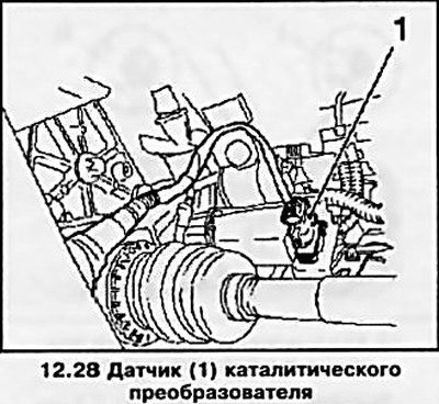
28. Raise the vehicle on a lift and disconnect the catalytic converter lambda probe wiring connector (see accompanying illustration).

28. Raise the vehicle on a lift and disconnect the catalytic converter lambda probe wiring…


29. Loosen the rear muffler retainer, release the muffler from the two holders and, with the help of an assistant, remove it (see illustration 12.4).

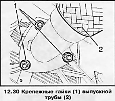
30. Loosen the 3 mounting nuts and disconnect the front exhaust pipe from the catalytic converter (see accompanying illustration).

30. Loosen the 3 mounting nuts and disconnect the front exhaust pipe from the catalytic converter…


31. Remove the exhaust pipe by disconnecting it from the front muffler (see illustration 12.6).


32. Remove the right engine boot (see Section 5) and drain the engine oil from the engine crankcase.

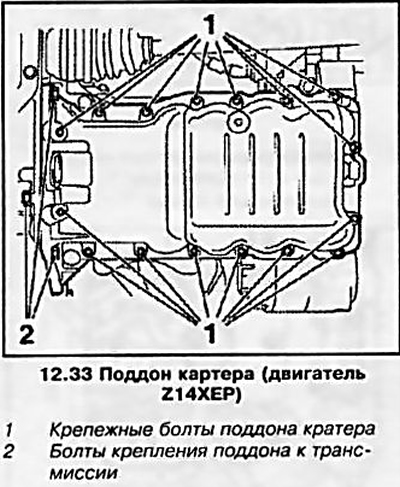
33. Remove 3 bolts securing the oil pan to the transmission, and then 16 more bolts securing it to the engine block (see accompanying illustration) and remove the tray.

33. Remove 3 bolts securing the oil pan to the transmission, and then 16 more bolts securing it to…


34. Before installing the pan, clean all mating surfaces from the remains of old gaskets. Install all removed components in the reverse order of their removal, do not forget to replace all gaskets. When installing the pan, tighten all 19 pan mounting bolts by hand, and then tighten them with the required force.

Z17DTL/H Engines


35. Disconnect the cable from the negative battery terminal, remove the oil dipstick, raise the car on a lift and remove the engine crankcase protection (see Section 5).

36. Drain the engine oil from the oil pan (see Chapter 1, Section 6), do not forget to replace the drain plug sealing washer.

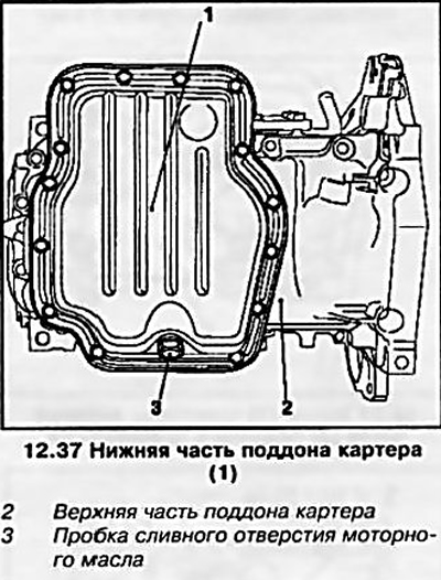
37. Remove the bottom of the tray (see accompanying illustration), having unscrewed 15 fastening bolts.

37. Remove the bottom of the tray (see accompanying illustration), having unscrewed 15 fastening…


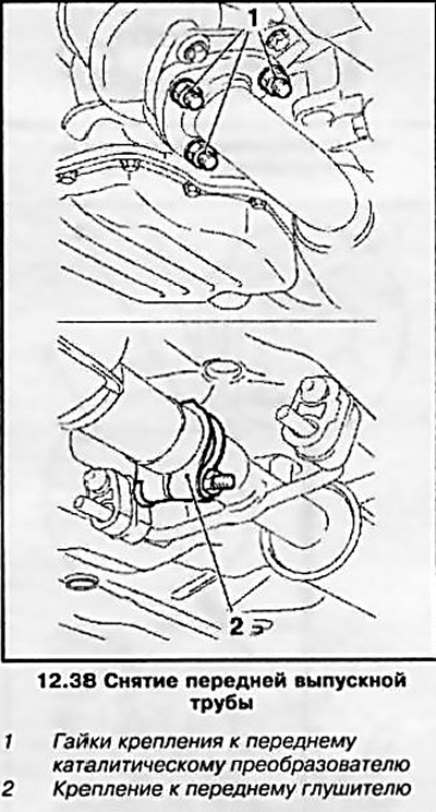
38. Remove the front exhaust pipe by disconnecting it from the front catalytic converter and from the front muffler (see accompanying illustration).


38. Remove the front exhaust pipe by disconnecting it from the front catalytic converter and from…


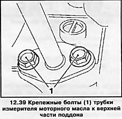
39. After unscrewing 2 bolts, disconnect the engine oil level dipstick tube from the top of the pan (see accompanying illustration).

39. After unscrewing 2 bolts, disconnect the engine oil level dipstick tube from the top of the pan…


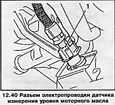
40. Disconnect the engine oil level sensor wiring connector (see accompanying illustration).

40. Disconnect the engine oil level sensor wiring connector (see accompanying illustration).


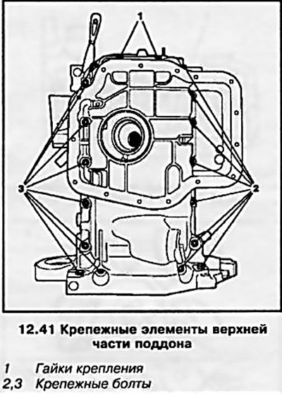
41. Unscrew the fastening elements of the upper part of the oil pan shown in the accompanying illustration and, using a suitable tool, (for example with a spatula), separate the pan from the engine block.

41. Unscrew the fastening elements of the upper part of the oil pan shown in the accompanying…


42. Before installing the pan, clean all mating surfaces from the remains of old gaskets. Installation of all removed components is carried out in the reverse order of their removal, do not forget to replace all gaskets. The upper and lower parts of the pan are installed on the sealant (gray color).


This article is available at russian, bulgarian, belarusian, ukrainian, serbian, croatian, romanian, polish, slovak, hungarian
Checking the article: Simonov Timofey

Share information:

Previous articles
Opel Astra H: Engine repair
Next articles

Removal and installation the cylinder head
Removal and installation of camshafts and valve lifters, checking the condition of components
Checking and adjusting the timing valves
Removal and installation the timing belt/chain (adjusting the valve timing)
Removal and installation a multi-ribbed accessory drive belt
Bringing the piston of the first cylinder to the top dead center (TDC) position at the end of the compression stroke
Removal and installation the oil pump
Removal and installation the engine oil level sensor
Removal, checking condition and installing flywheel/drive disk
Replacing crankshaft seals
Replacing camshaft seals
Checking the condition and replacing the powertrain suspension supports


Link to this page in different formats

Visitor comments


No comments yet


How much will 39 + 36 =


Astra J (2009-2015, petrol) 
  • General information
  • Vehicle device
  • User manual
  • Faults en route
  • Maintenance
  • Power unit
  • Engine repair
  • Cooling and lubrication system
  • Engine power system
  • Exhaust system
  • Transmission
  • Clutch
  • Car gearbox
  • Drive shafts
  • Chassis
  • Front suspension
  • Rear suspension
  • Steering
  • Brake system
  • Wheels and tires
  • Body
  • Exterior
  • Interior
  • Doors and windows
  • Body Care
  • Heating and air conditioning
  • Security systems
  • Electrical equipment
  • Equipment and devices
  • Lighting and signaling
  • Power devices
  • Electrical circuits
Astra H (2004-2009) 
  • General information
  • Introduction to the guide
  • Troubleshooting
  • User manual
  • Maintenance
  • Power unit
  • Engine repair
  • Cooling and heating
  • Power and exhaust system
  • Ignition system
  • Launch and charge system
  • Transmission
  • Mechanical gearbox
  • Automatic gearbox
  • Drive shafts
  • Chassis
  • Brake system
  • Car suspension
  • Steering
  • Body
  • Interior
  • Exterior
  • Electrical equipment
  • Equipment and devices
  • Electrical circuits
Astra G (1998-2004) 
  • General information
  • Introduction to manual
  • User manual
  • Maintenance
  • Power unit
  • SOHC gasoline engines
  • DOHC gasoline engines
  • Diesel engines 1.7 and 2.0
  • Engine repair
  • Cooling system
  • Supply system
  • Injection system (gasoline)
  • Injection system (diesel)
  • Exhaust system
  • Charge and launch system
  • Ignition system (gasoline)
  • Preheat system (diesel)
  • Transmission
  • Manual gearbox
  • Automatic gearbox
  • Clutch
  • Drive shafts
  • Chassis
  • Brake system
  • Wheel suspension
  • Steering
  • Body
  • Exterior
  • Interior
  • Doors and windows
  • Ventilation and heating
  • Electrical equipment
  • Equipment and devices
  • Electrical circuits
Astra G (1998-2004, petrol) 
  • General information
  • User manual
  • Car care
  • Maintenance
  • Power unit
  • Single shaft engines
  • Twin shaft engines
  • Engine repair
  • Cooling and heating
  • Fuel and exhaust systems
  • Starting and charging system
  • Ignition system
  • Transmission
  • Clutch
  • Mechanical gearbox
  • Automatic gearbox
  • Drive shafts
  • Chassis
  • Brake system
  • Car suspension
  • Steering
  • Body
  • Interior
  • Exterior
  • Electrical equipment
  • Equipment and devices
  • Wiring diagrams Opel Astra
  • Wiring diagrams Opel Zafira
Astra F (1991-1998, petrol) 
  • General information
  • Maintenance
  • Power unit
  • Engine in car
  • Engine removed
  • Cooling system
  • Heating and ventilation
  • Fuel supply (carburetor)
  • Fuel supply (injector)
  • Emission control
  • Ignition system
  • Transmission
  • Clutch
  • Mechanical gearbox
  • Automatic gearbox
  • Drive shafts
  • Chassis
  • Brake system
  • Car suspension
  • Steering
  • Body
  • Exterior
  • Interior
  • Electrical equipment
  • Equipment and devices
  • Electrical circuits
OpelBook.ru © 2017–2026 · Mobile version · · Sitemap: EN BG BY UA RS HR RO PL SK HU · Feedback · Site search
Astra F, petrol · Astra G, petrol · Astra G · Astra H · Astra J, petrol · Corsa B · Corsa C, petrol · Corsa C · Insignia A · Kadett D · Kadett E · Omega A · Omega B · Omega B2 · Vectra A, petrol · Vectra A · Vectra B, petrol · Vectra B · Vectra C · Zafira A, petrol · Frontera A, petrol · Frontera B · Ascona C · Vivaro A ·
We want your visit to be comfortable 🤝! We use cookies 🍪 to make that happen.