


Contents: Removal and installation the exhaust…⬇ Removal and installation of the…⬇ Removal and installation the diesel…⬇
1. The exhaust system of all models under consideration consists of three sections: intake, middle (intermediate) and rear. The main elements of the system are: the inlet pipe, the catalytic converter, the mufflers (central and additional), connecting tubular sections, mounting clamps, as well as support brackets and rubber loops by means of which the exhaust assembly is suspended from the underbody of the vehicle (see accompanying illustrations). The sections of the system are connected to each other by means of a single clamp connection (front section with intermediate) and one flange (intermediate section with rear). The joint of the middle and rear sections of the system is spring-loaded, which allows to compensate for the play that occurs during the movement of the car; in order to reduce the level of vibrations, a flexible insert is usually included in the receiving section of the system. Incorrect installation of the components and sections of the system leads to an increase in the level of noise and vibration transmitted to the car body.
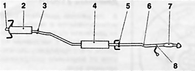
21.1a Exhaust system components for Z14XEP/Z16XEP engines
1 Exhaust pipe
2 Additional muffler
3 Exhaust tract connection points
4 Central muffler
6 Intake pipe
7 Flexible section of the inlet pipe
8 Lambda probe
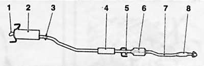
21.1b Z17DT(L/H) Engine Exhaust System Components
1 Exhaust pipe
2 Additional muffler
3 Exhaust tract connection points
4 Central muffler
6 Catalyst
7 Intake pipe
8 Flexible section of the inlet pipe
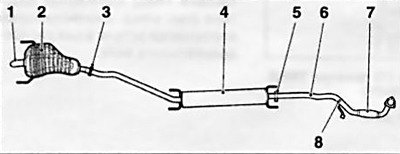
21.1c Z18XE Engine Exhaust System Components
1 Exhaust pipe
2 Additional muffler
3 Exhaust tract connection points
4 Central muffler
6 Intake pipe
7 Flexible section of the inlet pipe
8 Lambda probe
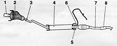
21.1d Z20LEL Engine Exhaust System Components
1 Exhaust pipe
2 Additional muffler
3.5 Exhaust tract connection points
4 Central muffler
6 Lambda probe
7 Intake pipe
8 Flexible section of the inlet pipe
2. Regularly inspect the entire system for signs of corrosion, deformation and mechanical damage. Check the reliability of the fasteners. A breach of the tightness of the components and their joints is fraught with the ingress of exhaust gases into the car interior. Defective components and sections are subject to replacement.
3. When working with the exhaust system, the following instructions must be followed:
- a) Pre-lubricate the fasteners to be released with penetrating oil or other rust-dissolving substance.
- b) Prepare the necessary replacement gaskets, suspension loops, clamps and fasteners in advance; when removing, all seals and fastening elements must be replaced;
- c) The sealing surfaces of the parts to be re-installed should be cleaned with a wire brush or sandpaper. Before installation, lubricate the threaded part of the fastener with anti-seize sealant;
- d) When installing components, ensure that there is sufficient clearance between the system sections and adjacent suspension/body components. Pay particular attention to the correct installation and secure fastening of heat shields (with appropriate equipment).
Note: If the system is severely damaged by corrosion, a gas cutter may be required to undock its sections (alternatively, you can use a metal hacksaw or a pneumatic chisel — do not forget to wear protective glasses and gloves.
4. When removing or disconnecting the intake pipe, do not allow it to hang on the flexible section of the pipe (see accompanying illustration). Bending the flexible section at an angle of 5-10° and twisting at an angle of ±0.5° can lead to its damage and failure. For this reason, when performing the corresponding work, the intake pipe should be secured with wire to rigid elements of the bottom, if necessary, use the help of an assistant.
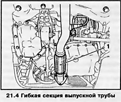
Removal and installation the exhaust pipe/catalytic converter
Removal
5. To perform a number of works in the engine compartment, it is necessary to remove only the exhaust pipe. To dismantle it, lift and place the car on stands, if equipped, remove the engine crankcase protection (see Chapter 2).
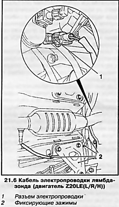
6. Z20LE(L/R/H) Engine: Disconnect the lambda probe wiring connector (see accompanying illustration) and release the wire from the retaining clips.
7. Disconnect the exhaust pipe (see accompanying illustration) from the catalytic converter (with appropriate equipment), for which you need to loosen 3 nuts.
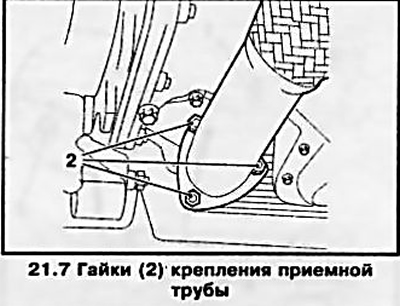
Note: On some models, the catalytic converter is part of the intake section and is removed with it.
8. Secure the central muffler to the bottom using wire.
9. Disconnect the intake pipe from the central muffler. If necessary, remove the lambda probe from the pipe.
Installation
10. Lubricate the lambda probe threads with a thin layer of Opel heat-resistant mounting paste (petrol engine: black grease, diesel engine: white grease), put it back in place.
Attention: The mounting paste should be applied only to the threads, do not allow it to come into contact with the lambda probe body!
Note: If the lambda probe is installed without using heat-resistant grease, the thread will start to stick over time. As a result, it will be impossible to unscrew the probe during the next service. New sensors already have the necessary grease.
11. Further installation is carried out in the reverse order of removal. Do not forget to replace the gas joint seals
Removal and installation of the exhaust system
Removal
12. Raise and place the vehicle on stands; if equipped, remove the engine crankcase guard (see Chapter 2). If the central section of the exhaust tract does not have holders, it must be secured with wire to the bottom of the car.
13. First remove the rear section of the exhaust system by disconnecting the rear connecting connection and removing the section from the holders (see accompanying illustration).
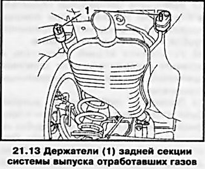
14. Then disconnect the inlet pipe from the catalytic converter, if necessary, remove the lambda probe (see above).
15. Remove the center muffler from the holders (see accompanying illustration) and remove it together with the exhaust pipe. If necessary, disconnect the exhaust pipe from the central muffler by disconnecting the front joint of the exhaust tract.
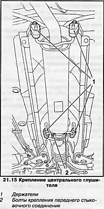
Installation
16. Secure the exhaust pipe to the catalytic converter with a new seal, do not tighten the mounting nuts.
17. Install the center muffler into the holders (hang with wire) and connect it to the intake pipe, do not tighten the fastening.
18. Install the rear muffler and insert it into the holders and, without tightening the fastener, connect it to the central muffler.
19. Check that the exhaust system is installed in accordance with the profile of the bottom and that there is no stress on the exhaust pipes due to bending. At the same time, make sure that there is sufficient distance between the exhaust system and the body everywhere, the holders with elastic rubber elements must be evenly loaded.
20. Tighten the exhaust system fastening elements.
21. Reinstall the lambda probe and crankcase guard, if they were removed, and lower the vehicle.
Removal and installation the diesel particulate filter (DPF) (Z19DT(H) engine)
22. Remove the rear section of the exhaust system (see above).
23. Mark the position of the differential pressure hoses (see accompanying illustration) soot filter and disconnect them.
Source is on the website: opelbook.ru
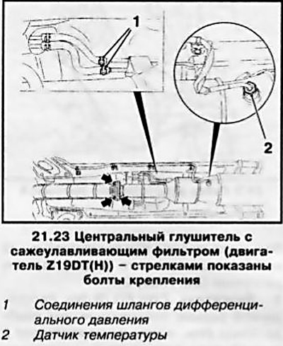
24. Loosen the union nut, remove the temperature sensor and move it to the side (see illustration 21.23), then unscrew the 3 mounting bolts and remove the central muffler from the holders together with the filter.
24. Installation is carried out in reverse order.
Attention: If the particulate filter has been replaced, the engine management system must be reprogrammed - contact an Opel service station!
Visitor comments