
General information
1. Electronic control system (see resist. illustration) The engine regulates the amount of fuel supplied to the cylinders and controls the ignition process.
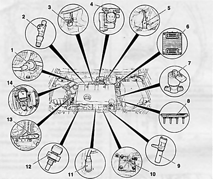
13.1 Sensors and modules of the engine management system (on the example of the Z18XE engine)
1 EVAP system valve
2 fuel injection injector
3 knock sensor
4 Throttle control module
5 Post-catalytic lambda probe
6 Electronic module of the engine management system
7 Exhaust gas regeneration system valve
8 Ignition module (DIS)
9 Crankshaft position sensor
10 Oil level sensor
11 Pre-catalytic lambda probe
12 Coolant temperature sensor
13 Camshaft position sensor
14 Air mass sensor
2. The electronic engine management system provides the following features:
- a) Accurate fuel dosage in any operating mode, which ensures low fuel consumption at high power;
- b) Reducing the content of toxic components in exhaust gases due to accurate fuel dosing and the use of a catalytic converter;
- With) Self-diagnosis of the engine management system provides the ability to quickly troubleshoot. One of the most important elements of the engine management system is the self-diagnosis subsystem. If during operation a failure of the functioning of any of the elements of the system is detected, the corresponding fault code is entered into the memory of the ECM processor. Reading and identification of stored codes (see chapter 5) allows you to quickly identify and eliminate the cause of the failure.
3. Engine control unit (ECM) plays the role of a think tank and is equipped with a high-speed microprocessor. Based on the analysis of data continuously received from information sensors, the ECM determines the optimal injection moment and the required amount of injected fuel. This also takes into account information processed by the transmission and engine immobilizer control modules.
4. Elements of the engine management system maintain high performance for a long time and practically do not need maintenance. Only such system elements as the air filter and spark plugs need regular replacements during vehicle maintenance. Serious adjustment and repair work requires the use of sophisticated diagnostic tools, which is why their execution should be entrusted to the specialists of the service station.
5. Adjusting idle speed and carbon monoxide concentration (SO) not required for maintenance purposes.
Safety measures when working on the engine management system
See also the list of safety precautions in Section 1 of this chapter.
6. Remember that the fuel inside the power system path with the engine running and the ignition on is under pressure. Residual overpressure continues to be retained in the system for some time after switching off the ignition and must be released before disconnecting the components / disconnecting the fittings!
7. Do not touch or disconnect the ignition wiring while the engine/starter is running.
Attention: Persons with an implanted pacemaker should never be allowed to service the elements of the ignition system!
Connection and disconnection of measuring instruments must also be carried out with the ignition off.
8. The fuel lines must be disconnected with the ignition off.
9. When performing work on checking the compression pressure in the cylinders (see chapter 2) the ignition and fuel supply system must be turned off.
Instructions for checking the engine management system
Attention: Malfunctions in the electronic control system can only be eliminated with the help of special tools - any non-professional intervention can lead to a malfunction of the system!
10. Before starting to search for the causes of failures using diagnostic tools, in order to exclude the influence of extraneous factors, it is necessary to check and fulfill the following conditions:
- There must be fuel in the tank;
- The engine must be mechanically sound;
- The battery is charged;
- The starter rotates with the required number of revolutions;
- The ignition system is working;
- Leaks and pollution in the fuel system are eliminated;
- The crankcase ventilation system is in good condition;
- The power unit is securely grounded to body ground.
Errors when starting the engine must be excluded - the correct sequence of the procedure for starting the engine is given in Chapter «Controls and methods of operation».
11. To determine the malfunction, you must connect to the diagnostic connector (see chapter 5) special device TESN-2 and display diagnostic codes from the memory of the ECM processor.
12. If, after completing the search and elimination of the causes of failures, the engine immediately stalls after starting, the cause of this phenomenon may be the blocking of the anti-theft system - interrogate the processor memory, if necessary, adjust the corresponding control unit.
Twinport system
13. The models described in this manual may be equipped with small engines with the Twinport system (see resist. illustration). Air enters each cylinder of the engine through two air channels. One of the channels can be blocked by an adjusting damper on a signal from the ECM, the damper position is controlled by a drive rod from the vacuum regulator. When the channel is blocked, a vortex flow of the air-fuel mixture is created, which allows the use of lean mixtures at low engine loads and when it is idling, thereby reducing overall fuel consumption.
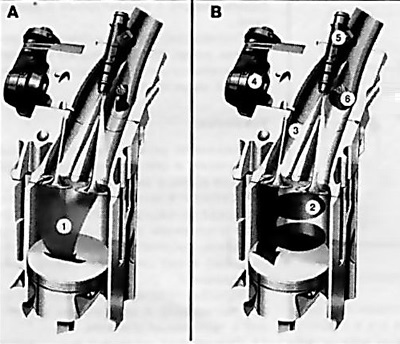
13.13 Twinport system (Z14XEP engine)
A Control flap open (at full load).
B Control flap closed (when the engine is running at idle and when the car is stopped).
1, 2 Air-fuel mixture flow direction
3 Inlets
4 Vacuum regulator
5 Injector
6 Control flap
Visitor comments