
Note: A new fuel pump cover o-ring will be required during installation.
General information
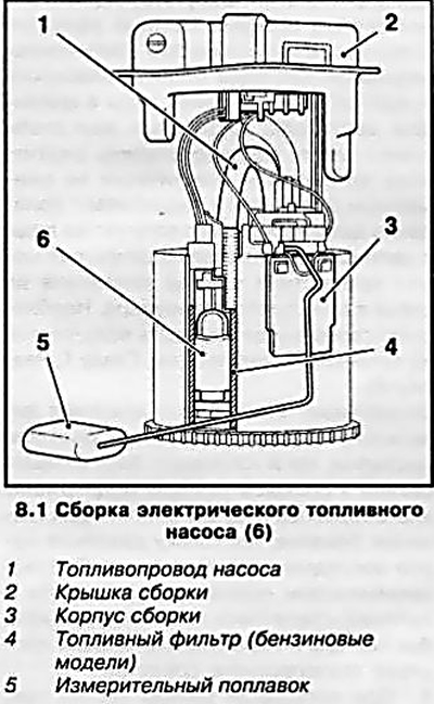
1. An electric fuel pump, together with a fuel reserve sensor, is installed in the assembly housing (see resist. illustration), which is immersed in the fuel tank. On gasoline models, a strainer fuel filter is installed in the same assembly.
Note: On diesel models, the fuel filter is located in the engine compartment.
2. Below is the procedure for removing the fuel pump for the Astra range. Removing the fuel pump on Zafira models is carried out in the same way, but after removing the fuel tank (see Section 12).
Note: Older diesel models may also lack a special hatch and require the removal of the fuel tank.
3. When performing work, the fuel tank must not be filled with more than ⅔ of its capacity. Before removing the fuel pump assembly, empty the fuel tank to the required level by consuming fuel while the vehicle is moving, or by pumping fuel with a special pump through the tank filler neck. Work should be carried out in a well-ventilated area.
Removing
4. Disconnect the negative cable from the battery (see chapter 5). Relieve pressure in the fuel supply system (see section 2).
5. In order to gain access to the hatch in the floor panel, lift and remove the rear seat cushion (see chapter 11).
Note: If necessary, remove the rear seat back as well.
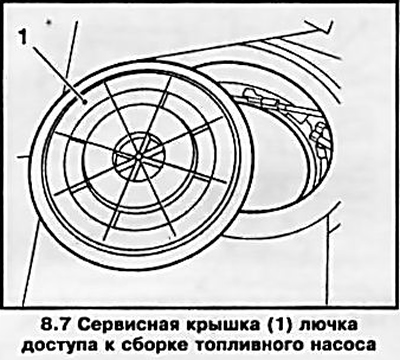
6. Fold back the carpet over the service hatch cover. Note: The area of the carpet above the hatch has already been cut, but on newer vehicles there may be connecting bridges - carefully cut through with a sharp knife.
7. Pry and remove the service hatch cover (see resist. illustration) access to the fuel pump assembly.
8. Disconnect the wiring connector (see resist. illustration) - fix the harness by gluing it with adhesive tape to the floor panel. Clearly mark, so as not to confuse during installation, the fuel lines, disconnect them from the fittings on the cover of the pump assembly. Plug the fuel lines immediately with suitable plugs to prevent fuel spillage and lay them aside. Remove traces of fuel leaks.
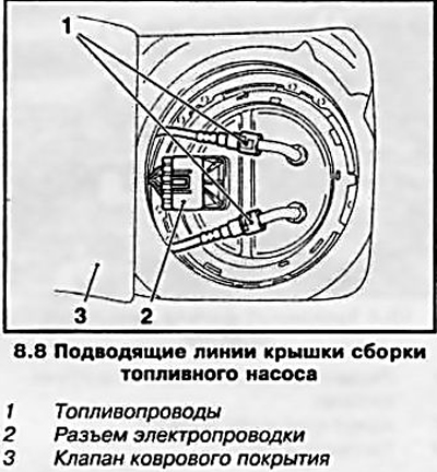
Note: When fuel lines are equipped with quick couplings, a special tool, such as HAZET 4501-1, is required to disconnect them.
9. Install special tool KM-797 (see resist. illustration) into the grooves of the retaining ring, unscrew and remove the ring. If no tool is available, place a plastic wedge or suitable wooden block in the groove of the retaining ring and unscrew the ring with light blows from a plastic or wooden hammer.
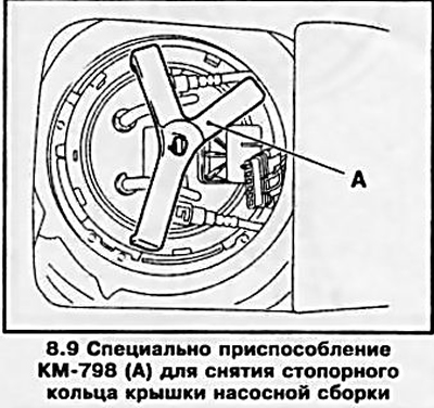
Attention: Never use metal objects for this - there is a risk of sparks during impacts!
10. Gently pull the cover up - it is connected to the body of the assembly by cable connectors and hose connections (see illustration 8.1). After removing the cover, disconnect all supply lines and the sealing ring from the inside of the cover.
Note: The sealing ring must be replaced without fail.
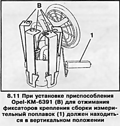
11. Install four elements of the KM-6391 tool into special sockets on the pump assembly housing (see resist. illustration), pay attention to the position of the measuring float! Press simultaneously on all elements of the fixture down to release the latches and remove the casing of the pump assembly. In the absence of a special tool, use a suitable tool and the help of an assistant.
12. Check the condition of the mesh filter, if necessary, replace it. If necessary, the pump can be removed from the assembly housing - try to remember the order of connecting the appropriate electrical wiring.
Installation
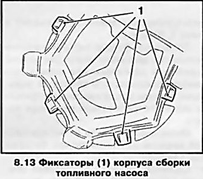
13. Reinstall the pump and strainer (if filmed), carefully place the pump assembly body into the tank and securely fasten it in the latches (see resist. illustration).
14. Further installation is carried out in the reverse order of removal. Remember to replace the fuel pump assembly cover gasket and check the system for leaks after installation is complete.
Note: The service cover and rear seat are installed after checking the tightness of the system.
Visitor comments