
General information
Engine cooling system
All models of vehicles discussed in this manual are equipped with a positive pressure engine cooling system with thermostatically controlled circulation of the working fluid. The water pump is fixed on the engine block and provides pumping of the coolant through the cooling path of the latter. The flow of fluid washes the areas where each of the cylinders in the block is located, after which it is directed to the rear of the engine. Cast-in-the-block and cylinder-head cooling ducts provide intensive cooling for intake and exhaust ports, spark plug areas and exhaust valve guides. The general scheme of operation and components of the cooling system are presented in the accompanying illustrations.
A typical diagram of the functioning of the cooling system of an internal combustion engine
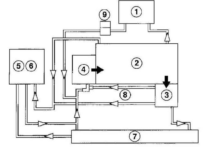
1 - Heater
2 - Power unit
3 - Thermostat
4 - Water pump
5 - Expansion tank
6 - Cover with valve
7 - Radiator
8 - Bypass hose
9 - Oil cooler
Cooling system components using the C14SE engine as an example
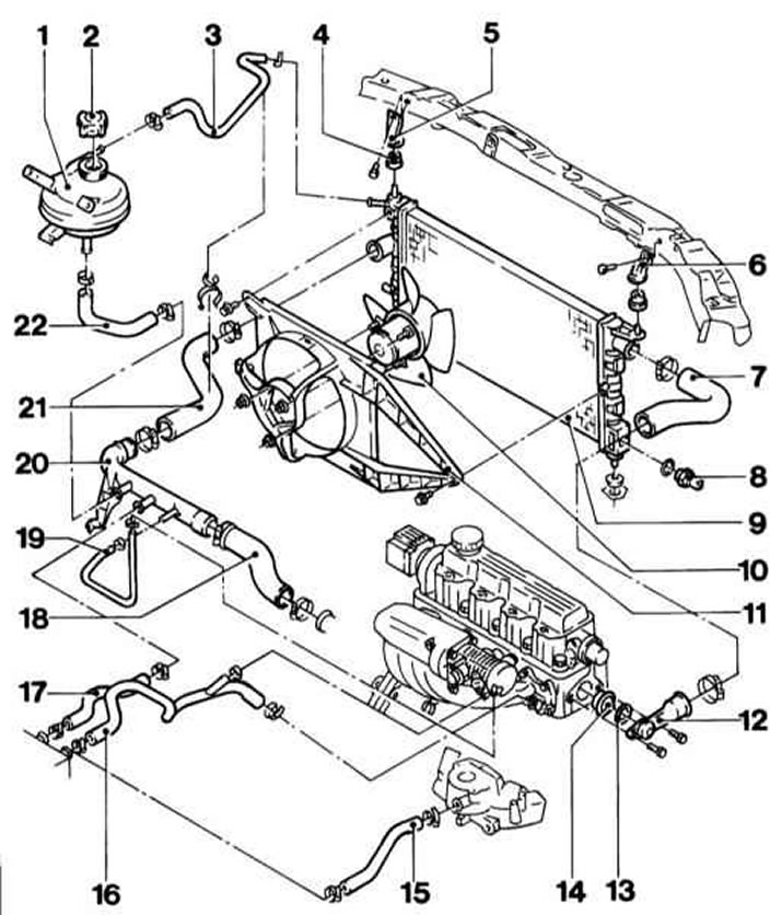
1 - Reservoir
2 - Cover
3 - Hose to the expansion tank
4 - Rubber support
5, 6 - Radiator bracket
7 - Upper radiator hose
8 - Thermal switch e / motor fan
9 - Radiator
10 - E / fan motor
11 - Fan case
12 - Thermostat housing
13 - O-ring
14 - Thermostat (coolant temperature controller)
15 - heater hose (only X12SZ and C14NZ engines)
16, 17 - heater hose
18 — Connecting hose of the water pump with a pipe
19 - Connecting hose coolant pipe with throttle valve
20 - Coolant pipe
21 - Lower radiator hose
22 - Connecting hose coolant pipe with reservoir
From the moment the engine is started, the cooling system goes through three modes of operation: at the first stage, until the temperature of the coolant has risen above a certain value, it circulates in a small circle from the working circuit of which the radiator is excluded. As the liquid warms up further, the poppet valve of the air-filled thermostat included in the system path opens and a radiator is included in the circulation circuit. Further, when the coolant temperature reaches the next control value, a temperature-sensitive sensor-switch is activated, which activates the cooling system fan, which pumps additional air flow, which significantly increases the efficiency of the radiator heat exchanger.
The cooling system is hermetically sealed and tightly sealed with a radiator cap capable of withstanding a certain overpressure, which increases the boiling point of the coolant and, accordingly, the efficiency of heat removal through the radiator. When the internal pressure in the system exceeds a certain value, the spring-loaded plate of the safety valve mounted in the radiator cap rises above its seat, ensuring that excess coolant flows through the connecting (overflow) tube into the expansion tank. As the system cools down, the fluid automatically returns from the reservoir to the radiator.
Coolant is added to the system through the expansion tank neck (see chapter Vehicle settings and routine maintenance), which at the same time also acts as a receiver, accumulating the excess liquid displaced from the radiator.
In view of the above design features, such a cooling system is called closed, since it excludes any functional loss of the working fluid.
Interior heating and ventilation systems
The main components of the interior heating system are a 4-speed electric fan and a heat exchanger, placed in a box-shaped heater casing, fixed under the dashboard of the car. The heat exchanger is connected to the engine cooling system through rubber hoses. The control unit for the functioning of the heater / air conditioner is mounted in the instrument panel of the car. The coolant heated in the engine circulates through the heater heat exchanger, giving off its heat to the air filling the casing. When the interior heating is turned on, the leaf damper opens, as a result of which the internal volume of the heater casing is connected to the volume of the passenger compartment. When the fan is turned on, the impeller of the latter begins to drive the air supplied to the passenger compartment through the heat exchanger, providing it with intensive heating.
Interior heating and ventilation components
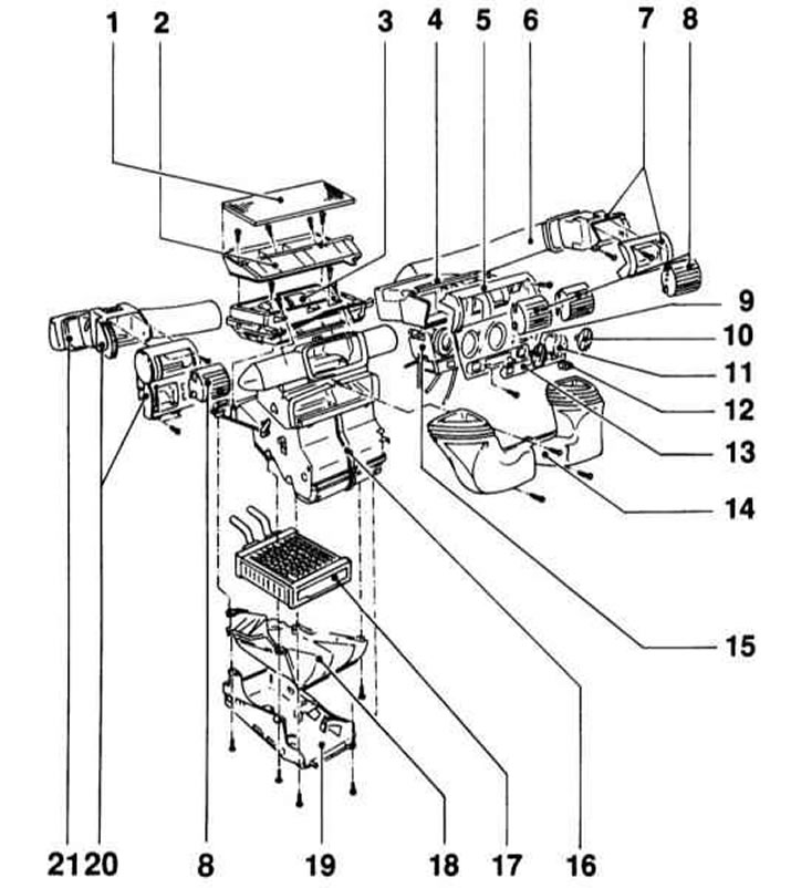
1 - Air filter
2 - Air filter housing
3 — the Case of a ventilating damper
4 — the Case of the central deflector
5 - Heater control unit panel
6 - Right air duct
7 - Right deflector
8 - Deflector grille
9 — The handle of a regulator of temperature of air
10 — The handle of switching of the directions of air supply
11 - Knob for selecting fan speed and rear window heating
12 - Air circulation mode switch
13 — the Switch of heating of a forward seat
14 - Air duct for blowing the wind inlet
15 - Heater control unit
16 - Air distributor housing
17 - Heating element
18 - Heating element support
19 - Air distributor housing
20 - Left deflector
21 - Left air duct
Air is supplied to the cabin through the front level deflectors (two central and two side), footwell nozzles and windshield deflectors.
The rules for using the controls for the operation of heating, ventilation and air conditioning systems are detailed in Chapter Controls and methods of operation at the beginning of the guide.
Air conditioning system
The optional air conditioning system includes a condenser mounted in front of the radiator, an evaporator located next to the heat exchanger of the heater, a compressor mounted on the engine block, and a filtering receiver-drier (battery), equipped with a high pressure reducing valve. All components are interconnected by refrigeration lines. The principle of operation of the air conditioning system is explained in the accompanying illustration.
The principle of operation of the air conditioning system
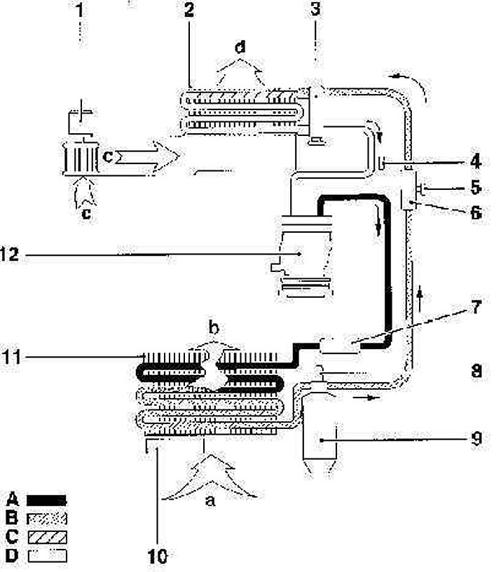
1 - Fan
2 - Evaporator
3 - Expansion valve
4 - Service connector of the low-pressure circuit
5 - Service connector of the high-pressure circuit
6 - Pulsation damper
7 - Pulsation damper
8 — Sensor-switch pressure
9 - Receiver-drier
10 - Additional fan
11 - Capacitor
12 - Compressor
a - Inlet flow of cold air driven through the condenser heat exchanger
b - Outlet stream of heated air driven through the condenser heat exchanger and taking heat from the refrigerant
c - Airflow generated by the fan
d - Air flow through the evaporator heat exchanger
A - Gas phase of the high-pressure circuit
B - Liquid phase of the high-pressure circuit
C - Liquid phase of the low-pressure circuit
D - Gas phase of the low-pressure circuit
The fan drives the air entering the passenger compartment through the evaporator heat exchanger, which operates in a mode opposite to that of the radiator. The refrigerant pumped through the heat exchanger boils and, evaporating, takes away excess heat from the air. The temperature inside the passenger compartment is then reduced to the required comfortable value (operator's choice). The compressor circulates the refrigerant in the system by pumping the heated liquid through the condenser, where it is cooled and returned to the evaporator.
The rules for using the controls for the operation of heating, ventilation and air conditioning systems are detailed in Chapter Controls and methods of operation at the beginning of the guide.
Precautionary measures
To avoid scalding, never remove the expansion tank cap or disconnect any components of the cooling path when the engine is hot. If it becomes necessary to remove the expansion tank cap before the coolant has completely cooled, (although such situations should be avoided whenever possible), you must first relieve excess pressure in the system. Wrap the tank cap with a thick layer of rags, then slowly unscrew until a hiss occurs. When the hissing noise indicating release of steam stops, slowly unscrew the lid all the way. If the hissing does not resume at the last stage of unscrewing, the cap can be removed. During the entire procedure, do not tilt your face over the neck of the tank; wear rubber gloves to protect your hands.
Try to avoid getting antifreeze on exposed skin and paintwork on body panels. Accidental splashes should be washed off immediately with plenty of clean water. Never leave drained or fresh engine coolant stored in an open container. Collect traces of the strait immediately with rags. Remember that the sweet smell of antifreeze can attract the attention of children and animals. The ingress of even a small amount of coolant into the digestive tract of a living organism is fraught with the most serious consequences, even death.
Visitor comments