


Note: On models equipped with the OBD II self-diagnostic system, the nameplate under the hood should have the following entry: "OBD II compliant".
1. With the introduction of the latest environmental legislation, the requirements for controlling the content of toxic waste in exhaust gases have become more stringent. This in turn has led to the equipping of cars with more sophisticated engine management systems. The main element of the system is the on-board processor, more often called the electronic control module (ECM).
2. All models described in this Manual are equipped with a second-generation on-board diagnostics system (OBD-II), which allows checking sensors and actuators, controls vehicle service cycles, provides the ability to memorize even short-term failures during operation and clear the memory unit. Reading the processor memory data is performed using a special scanner connected to the 16-pin diagnostic connector for reading the database (DLC). The diagnostic connector is located on the center console. On Astra models, to gain access to the connector, it is necessary to remove the decorative cover under the parking brake lever (see illustration 3.2a), on Zafira models remove the gearshift lever base cover (see Chapter 11), and if the console is equipped with an ashtray, remove the ashtray (see Chapter "Controls and operating techniques", Section 17) (see illustration 3.2b).
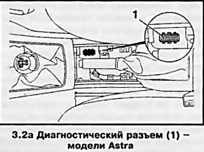
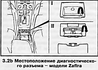
3. Before connecting diagnostic devices, it is necessary to make sure that the battery is in good condition and fully charged and perform other checks as specified in Chapter 4, Section 13.
4. Information is collected using diagnostic equipment (see accompanying illustration). It should be remembered that, as a rule, such equipment is designed for a specific model or model range of cars; changing the control system by even one element leads to a change in all electrical circuits.
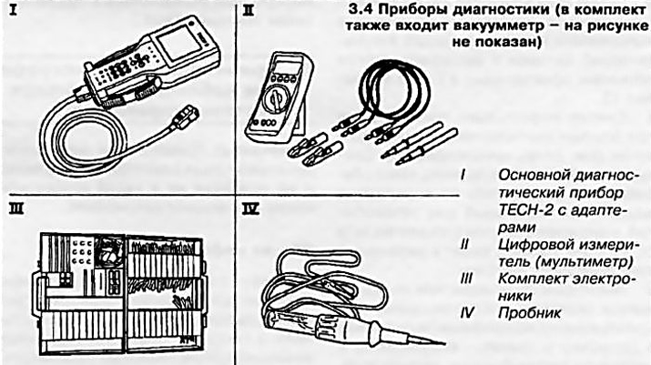
5. Some manufacturers have started producing scanners designed for use by amateur mechanics at home - ask in car accessories stores. Service stations may use an expensive specialized diagnostic computer, specially designed for full diagnostics of most systems of modern cars. Diagnostic scanners and computers allow you to read and print diagnostic codes, as well as the basic electrical circuit diagrams stored in the memory of the control module (if any are included), program the anti-theft system, monitor signals in fuse circuits in real time.
6. When a malfunction is detected, the ECM issues a command to turn on the instrument cluster-mounted "Check Engine" warning lamp, also called the malfunction indicator lamp (MIL). At the same time, the control unit switches to the emergency mode. The lamp will remain on until the self-diagnostic system memory is cleared of the detected malfunction codes stored in it (see below).
7. Reading of OBD-II system data is performed using a special TESN-2 scanner (see illustration 3.4), connected to the 16-pin diagnostic connector (DLC) via an adapter - proceed in accordance with the instructions of the device menu. The list of codes of the main malfunctions of the power unit is given in the Specifications at the beginning of this Chapter. The same scanner is also used to clear the processor memory. It is recommended that the procedures for reading DTC codes and clearing the ECM memory be entrusted to service station specialists.
8 Maintenance of engine management/exhaust gas reduction components is subject to special extended warranty obligations. No attempt should be made to diagnose ECM failures or replace system components on your own until the deadline for these obligations expires — Please contact your Opel representative for more information.
Visitor comments