


Contents: Information about diagnostic devices ⬇ General description of the OBD system ⬇ Information sensors (depending on…⬇ Executive devices ⬇ Reading fault codes and clearing…⬇ Clear OBD memory ⬇
The material below is for descriptive purposes only and is not tied to any specific make or model of vehicle.
Information about diagnostic devices
The proper functioning of injection system components and exhaust gas toxicity reduction systems is checked using a universal digital meter (multimeter). Using a digital meter is preferable for several reasons. Firstly, it is quite difficult to measure the value of an analog meter (sometimes it's impossible), determine the result of the reading with an accuracy of up to hundredths and thousandths, while when examining circuits that include electronic components, such accuracy is of particular importance. The second, no less important, reason is the fact that the internal circuit of the digital multimeter has a fairly high impedance (the internal resistance of the device is 10 million ohms). Since the voltmeter is connected to the circuit being tested in parallel, the accuracy of the measurement is higher, the smaller the parasitic current that passes through the device itself. This factor is not significant when measuring relatively high voltage values (9÷12 V), but it becomes decisive when diagnosing elements that produce low-voltage signals, such as, for example, a lambda probe, where we are talking about measuring fractions of a volt.
The most convenient devices for diagnosing engine management systems of modern car models are hand-held scanner-type readers. First-generation scanners are used to read OBD-I system fault codes. Before use, the reader should be checked for compliance with the model and year of manufacture of the vehicle being tested. Some scanners are multifunctional due to the ability to change the cartridge depending on the model of the vehicle being diagnosed (Ford, GM, Chrysler, etc.), others are tied to regional government requirements and are intended for use in specific areas of the world (Europe, Asia, USA, etc.).
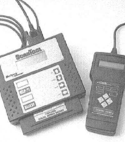
Recently, such reading devices as hand-held scanners like Actron Scantool or AutoXray XP240 have become absolutely indispensable in diagnosing engine management systems of modern cars
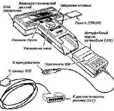
Diagnostic scanner New Generation Star (NGS) (also widely used scanners are FDS 2000, Bosch FSA 560 and KTS 500 [0 684 400 500])
With the introduction of the second generation of on-board diagnostics (OBD-II) systems that meet the latest environmental protection legislation, specially designed readers have begun to be manufactured. Some manufacturers have started producing scanners designed for use by amateur mechanics at home - ask in car accessory stores. Another very convenient diagnostic device is an expensive specialized diagnostic computer (type ADC2000 from Launch HiTech), or a regular personal computer complete with a special cable and adapter (set 1 687 001 439). Some scanners, in addition to the usual diagnostic operations, allow, when connected to a personal computer, to print out the basic diagrams of the electrical equipment stored in the memory of the control module (if any are included), program the anti-theft system, observe signals in the fuse circuits in real time.
Adapter for matching diagnostic lines K and L with the COM port of the computer
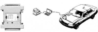
In principle, reading the fault codes stored in the self-diagnostic system memory can be done using the MIL malfunction indicator lamp and a jumper wire installed between specific terminals of the 16-pin diagnostic connector.
General description of the OBD system
On modules equipped with the OBD II system, the nameplate installed under the hood must contain the entry "OBD II compliant", and the DLC diagnostic connector must be 16-pin. As a rule, the OBD II system is mandatory for models intended for the North American market, starting from 1996, as well as European models, starting from 2000.
The OBD system includes several diagnostic devices that monitor individual parameters of the toxicity reduction systems and record detected failures in the on-board processor memory in the form of individual fault codes. The system also checks sensors and actuators, monitors vehicle operating cycles, and provides the ability to freeze parameters and clear the memory block.
All models described in this Manual are equipped with a second-generation on-board diagnostics system (OBD-II). The main element of the system is the on-board processor, more often called the electronic control module (ECM). The ECM is the brain of the engine management system. Initial data comes to the module from various information sensors and other electronic components (switches, relays, etc.). Based on the analysis of data received from the information sensors and in accordance with the basic parameters stored in the processor memory, the ECM generates commands to operate various control relays and actuators, thereby adjusting the engine operating parameters and ensuring maximum efficiency with minimum fuel consumption. The OBD-II processor memory data is read using a special scanner connected to the 16-pin diagnostic database connector (DLC), located under the decorative cover on the center console in front of the parking brake lever.
OBD II diagnostic connector - use standard OBD-II J1962 cable when connecting
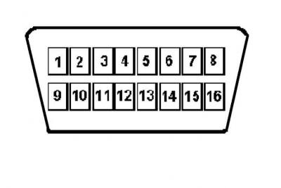
The purpose of some of the pins of the standard 16-pin DLC connector of the OBD II system:
1 - 2 — Data exchange bus "
3 — Data exchange line for AT, electronically controlled sunroof, single lock
4 - Connection to the body
5 — Housing - signal output
6 - Flashing code
7 — Line K for ECM data exchange, seat and mirror position memory (ISO 9141)
8 — Data exchange line for the cruise control, multifunctional information display, anti-theft alarm
9 - 11 - 10 — Data exchange bus "-"
12 — Data exchange line for ABS, traction control, safety systems, power steering
13 - 14 - 15 — Line L
16 - Protected by the battery fuse " (constantly under tension)
[Source is on this resource www.opelbook.ru]
In principle, reading the fault codes stored in the self-diagnostic system memory can be done using a jumper wire installed between specific terminals of the 16-pin diagnostic connector (refer to the illustrations).
Maintenance of engine management/exhaust gas reduction components is subject to special extended warranty obligations. You should not attempt to independently perform diagnostics of ECM failures or replace system components until the deadline for these obligations is reached. Please contact specialists from Opel's branded service stations.
Information sensors (depending on the vehicle configuration)
Oxygen sensors (lambda probes) - The sensor generates a signal, the amplitude of which depends on the difference in oxygen content (O2) in the engine exhaust gases and the outside air.
Crankshaft position sensor (CPS) - The sensor informs the ECM about the crankshaft position and engine speed. This information is used by the processor when determining fuel injection timing and setting the ignition timing.
Piston Position Sensor (CYP) - Based on the analysis of signals received from the sensor, the ECM calculates the position of the piston of the first cylinder and uses this information to determine the timing and sequence of fuel injection into the engine combustion chambers.
TDC sensor - The signals generated by the sensor are used by the ECM to determine the ignition timing settings at engine start.
Engine Coolant Temperature (ECT) Sensor - Based on the information received from the sensor, the ECM makes the necessary adjustments to the air-fuel mixture composition and ignition timing, and also monitors the operation of the EGR system.
Intake Air Temperature (IAT) Sensor - The ECM uses information from the IAT sensor to make fuel flow adjustments, spark advance settings, and control EGR system operation.
Throttle Position Sensor (TPS) - The sensor is located on the throttle body and is connected to the throttle shaft. The ECM determines the throttle opening angle based on the amplitude of the signal emitted by the TPS (controlled by the driver using the gas pedal) and accordingly adjusts the fuel supply to the combustion chamber intake ports. Sensor failure or loosening of its fastening leads to injection interruptions and disturbances in the stability of idle speed.
Absolute pressure sensor in the pipeline (MAP) - The sensor monitors variations in the depth of vacuum in the intake manifold associated with changes in crankshaft speed and engine load and converts the received information into an amplitude signal. The ECM uses the information supplied by the MAP and IAT sensors for fine adjustments to fuel delivery.
Barometric pressure sensor (BARO) - The sensor produces an amplitude signal proportional to changes in atmospheric pressure, which is used by the ECM to determine the duration of fuel injection moments. The sensor is integrated into the ECM module and is not serviceable individually.
Knock Sensor (KS) - The sensor reacts to changes in the vibration level associated with detonations in the engine. Based on the information received from the sensor, the ECM makes the appropriate adjustments to the ignition timing.
Vehicle Speed Sensor (VSS) - As its name suggests, the sensor informs the processor about the current speed of the vehicle.
EGR valve opening value sensor - The sensor notifies the ECM of the amount of displacement of the EGR valve plunger. The received information is then used by the processor to control the operation of the exhaust gas recirculation system.
Fuel tank pressure sensor - The sensor is an integral part of the fuel vapor trapping system (EVAP) and serves to monitor the pressure of gasoline vapors in the tank. Based on the information received from the sensor, the ECM issues commands to operate the electromagnetic valves for purging the system.
Power Steering Pressure Switch (PSP) - Based on the information received from the PSP switch, the ECM increases the idle speed by activating the Idle Speed Control (IAC) sensor to compensate for the increased engine loads associated with the operation of the power steering during maneuvers.
Transmission sensors - In addition to the data received from the VSS, the ECM also receives information from sensors located inside or connected to the transmission. These sensors include: (a) the secondary (main) shaft speed sensor and (b) the intermediate shaft speed sensor.
Air Conditioner Clutch Control Switch Sensor - When power is supplied from the battery to the A/C compressor solenoid valve, the corresponding information signal is sent to the ECM, which interprets it as evidence of an increase in engine load and adjusts its idle speed accordingly.
Executive devices
Fuel pump relay - The ECM activates the fuel pump relay when the ignition key is turned to position II or III. When the ignition is turned on, the relay is activated to increase the pressure in the fuel system. For more detailed information on the main relay, see Chapter Fuel, exhaust and emission control systems.
Fuel injector - The ECM ensures individual activation of each injector in accordance with the established firing order. In addition, the module controls the duration of the injector opening, determined by the width of the control pulse, measured in milliseconds and determining the amount of fuel injected into the cylinder. More detailed information on the operating principle of the injection system, replacement and maintenance of injectors is given in Chapter Fuel, exhaust and emission control systems.
Ignition Control Module (ICM) - The module controls the operation of the ignition coil, determining the required base advance based on commands generated by the ECM.
Idle Air Control Valve (IAC) - The IAC valve controls the amount of air bypassed around the throttle valve when the latter is closed or in the idle position. The ECM controls the opening of the valve and the formation of the resulting air flow.
Carbon adsorber purge solenoid valve - The valve is an integral part of the fuel evaporative emission (EVAP) system and, when triggered by the ECM, releases fuel vapors accumulated in the canister into the intake manifold for combustion during normal engine operation.
Carbon adsorber purge control solenoid - The solenoid is used by the ECM when the OBD-II system checks for proper operation of the EVAP system.
Reading fault codes and clearing processor memory
When a fault is detected that is repeated in two consecutive trips, the ECM issues a command to turn on the instrument cluster indicator lamp "Check Engine", also called the malfunction indicator (MIL). At the same time, the ECM switches to the emergency mode. The lamp will remain on until the memory of the self-diagnostic system is cleared from the codes of detected faults.
Reading codes with a scanner
Reading of fault codes is performed by connecting a special reader to the 16-pin diagnostic connector DLC, - proceed in accordance with the instructions of the device menu.
Reading Codes Using the MIL
1. Stop the engine and switch off the ignition. Open the decorative cover of the center console in front of the parking brake lever and short-circuit terminals A and B together (models produced up to 1995.), or short-circuit terminal 6 of the DLC connector to ground (models produced since 1995.), - proceed with extreme caution, try not to bend the terminals. It should be remembered that poor contacts in the terminal connections can cause the control module to fail or the processor memory to malfunction.
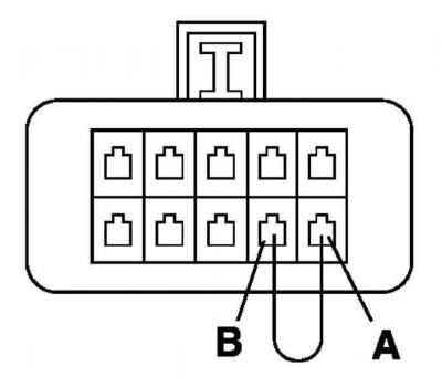
To read diagnostic codes for models up to 1995 using the MIL, short terminals A and B of the DLC connector
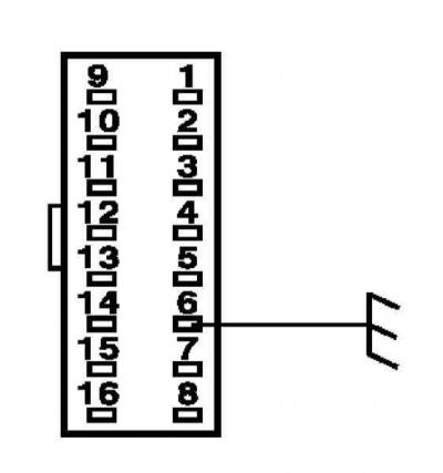
To read diagnostic codes on 1995 and later models using the MIL, ground terminal 6 of the 16-pin DLC connector to ground
2. Turn on the ignition. The diagnostic codes stored in the control module memory are read by the flashes of the malfunction indicator lamp MIL/"Check Engine" on the vehicle's instrument panel (see Chapter Controls and operating techniques at the beginning of the Guide).
3. Each fault code consists of two or three groups of flashes (digits). The number of flashes in a group corresponds to the value of the code digit. A short pause separates the code digits, a long pause serves to separate the codes. Each code is displayed three times in a row. The codes are displayed in ascending order of numbers. Zero corresponds to 10 flashes of the control lamp.
4. The displayed code allows you to determine only the system circuit whose failure was recorded by the self-diagnostic system. Thus, if the code indicates a malfunction of the coolant temperature sensor (ECT), the possibility of a malfunction of the control module itself cannot be ruled out. The truth can be established either by replacing the sensor or by carrying out appropriate control measurements.
5. When checking a circuit, first disconnect the corresponding electrical wiring and check the condition of its contact connections. If necessary, clean the terminals, completely removing traces of oxidation from them.
6. Check the reliability of the cable fastening at the cable lug.
7. Check the resistance of the suspect element - if the nominal resistance of the element is low, factors such as the accuracy and internal resistance of the measuring instrument should be taken into account.
8. Check the integrity of the wires going to the control module (if necessary, check the electrical connection diagrams provided in Chapter On-board electrical equipment).
9. When reading codes indicating excessive underestimation of the signal level, first of all, it is necessary to make sure that the corresponding component is grounded reliably. Overestimation of the signal level is most often associated with a break in the electrical wiring.
Information content of the 5-digit code bits of type P0380
Type code bits R 0 3 8 0 have the following meaning (from left to right):
1st rank | |
| P | power unit |
| B | body |
| WITH | chassis |
| U | communication buses for data exchange of control systems |
2nd category | Source of code |
| 0 | standard SAE |
| 1 | extended - manufacturer-defined |
3rd rank | System |
| 0 | the system as a whole |
| 1 | air mixing |
| 2 | fuel injection |
| 3 | ignition system or misfires |
| 4 | additional release control |
| 5 | car speed and idle control. |
| 6 |
input and output signals of the control unit |
| 7 | transmission |
4.5 ranks |
Component or circuit fault sequence number (00-99) |
Clear OBD memory
To clear the ECM memory, turn off the ignition, remove the jumper wire that grounds the DLC connector terminal, and disconnect the battery terminal for at least 60 seconds, or connect a scanner to the system and select the CLEARING CODES function in its menu (Removing codes), - then follow the instructions displayed on the device.
Clearing the OBD memory by disconnecting the negative battery cable will erase the engine settings and cause the engine speed to become unstable for a short time after initial start-up, as well as erase the clock and radio settings.
If your car stereo system is equipped with a security code, make sure you have the correct combination to activate the audio system before disconnecting the battery!
To avoid damaging the ECM, disconnect and connect it only with the ignition off!
The code stored in the memory is deleted automatically if the corresponding fault does not appear within 20 consecutive engine starts (the number of revolutions should not be less than 450 per minute).
Make sure that the system memory is cleared before installing new emission control components on the engine. If the fault memory is not cleared before starting the system after replacing a failed information sensor, the ECM will enter a new fault code. Clearing the memory allows the processor to reconfigure to the new parameters. However, for the first 15-20 minutes after the initial engine start, until the ECM has completed its adaptation, some instability of its speed may occur.
Visitor comments