
Removal and installation of an anther of the engine and protection of a crankcase of the engine
2. When carrying out many operations, in order to free access to the relevant units, it is required to remove the right engine boot on gasoline models, and the engine crankcase protection for diesel models.
3. First you need to jack up and place the car on stands or raise it on a lift.
4. To remove the right boot (see resist. illustration) unscrew 4 bolts and remove 2 rivets.
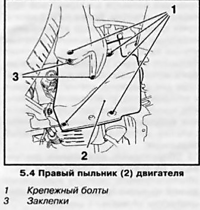
Note: In some cases it may be necessary to remove the right front wheel.
5. The crankcase protection has a service cover designed to release access to the drain plug on the crankcase to drain the engine oil - if necessary, unscrew the 4 bolts and remove the cover.
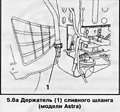
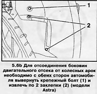
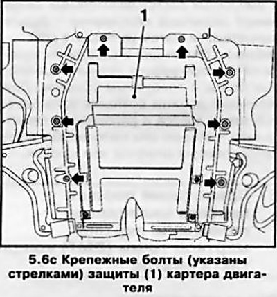
6. On Astra models, you must first release the drain hose from the holder on the right side of the engine compartment (see illustration 5.6a). Then, on both sides of the car, unscrew the mounting bolts, remove 2 rivets (see illustration 5.6b) and disconnect the sides of the engine compartment from the wheel arches. Remove 8 fixing screws (see illustration 5.6c) and remove the crankcase protection.
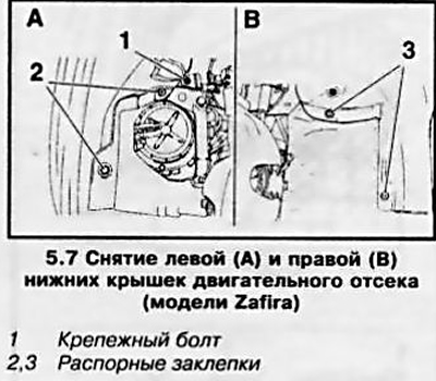
7. On Zafira models, you must first remove the lower side covers of the engine compartment, for which, on the left side, unscrew the fixing bolt and remove 2 rivets, and on the right side, remove only 2 spacer rivets (see resist. illustration). Further operations are performed in the same way as on Astra models.
8. Installation is carried out in the reverse order.
Installing the right/left engine mount remover
9. The design of the front suspension and the location of the drive units on the engines are designed in such a way that the toothed belt / chain, and in some cases the multi-ribbed belt, is installed around the right engine support. When carrying out work with the removal of belts, it is possible to dismantle the right support so as not to remove the engine from the car. Removal of the left pore is required to replace it, as well as when removing the engine (see Section 19) or transmission (see chapters 6 and 7).
10. A lifting device is required to carry out the work (hoist) with appropriate engine jacking or universal (for all engines described in this manual) a set of tools from Opel for holding the engine on the front subframe of the car during the removal / replacement of the support. Using a hoist is less convenient and sometimes even unacceptable. In some cases, a jack can be used to support the engine by placing a suitable size block of wood between the jack head and the engine.
11. The procedure for installing/removing the universal tool is described below.
12. Jack up and place the car on stands or raise it on a lift. Remove, if necessary, the right boot or crankcase protection (see above).
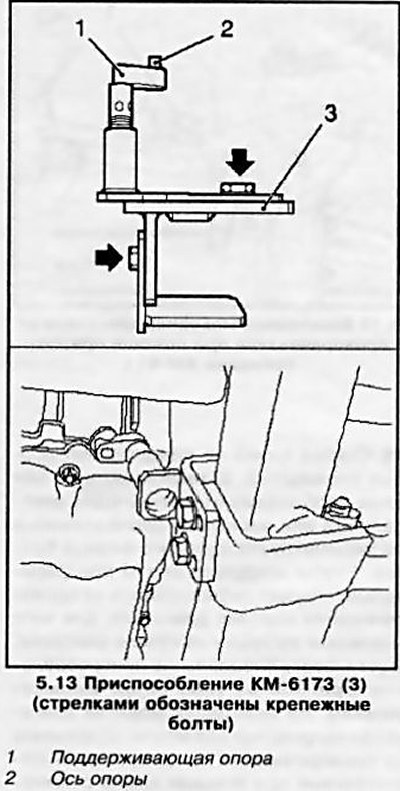
13. Loosen the 4 bolts of the KM-6173 tool (see resist. illustrations) and install the tool on the front subframe. Unscrew the supporting support of the device until it rests against the cylinder block, while the axis of the support should enter the hole in the block. Tighten the bolts.
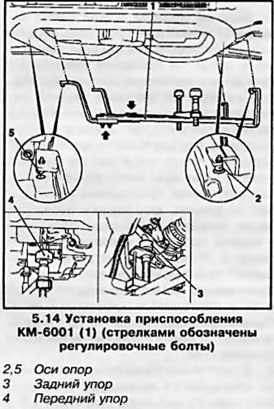
14. Prepare the KM-6001-A fixture (see resist. illustration) for installation on the corresponding engine model, for which loosen the 3 adjusting bolts and adjust the size of the fixture. Install the tool on the front subframe so that the axles of the tool supports fit into the guide holes on the subframe and tighten the 3 adjusting bolts. Adjust the height of the front and rear stops by twisting them up until they rest against the engine block - the device should be firmly fixed on the subframe without play.
15. Dismantling of devices is carried out in the reverse order.
Removal and installation of the crankshaft pulley
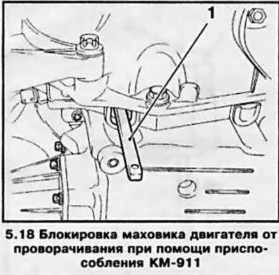
16. The pulley is mounted directly on the trunnion or on the crankshaft gear. On most engines, the pulley acts as a torsional vibration damper.
17. Before removing the pulley, the drive belt must be removed from it (see Section 7) and front boot/engine guard if they have not already been removed.
Note: In some cases it may be necessary to remove the right front wheel.
18. Removing the pulley is not particularly difficult. Depending on the model, it is necessary to unscrew one central or several bolts located around the perimeter of the mounting flange. To unscrew the bolts, you must first block the engine flywheel from turning, for which remove the plug on the flywheel dome and install the special tool Ore1-KM-91 (see resist. illustration). On some engine models, the crankshaft can be held from turning by the central hexagon using a socket wrench (in this case, the pulley mounting bolts are located along its perimeter).
19. If the gearbox was previously disconnected from the engine, the flywheel is blocked using a special stopper mounted on the engine housing (see illustration 15.2 to this Chapter).
20. To eliminate a malfunction when making a long trip, when it is not possible to jack up the car, etc., in order to block the crankshaft from turning, ask an assistant to turn on the highest gear and depress the foot brake pedal all the way (on models with manual transmission).
21. Do not forget to remove the locking devices if, after disconnecting the pulley, it will be necessary to rotate the crankshaft.
22. Before removal, if there are no special marks or mounting pins / keys for installing the pulley in a strictly defined position, you must remember its position on the mounting flange / crankshaft shank - mark yourself with a core or marker.
23. Installation of a pulley is made in an order, the return to its removal. Tighten the fixing bolts to the required torque (see specs). When installing, use only new bolts.
Removal and installation of gear wheels of camshafts
Withdrawal
24. This subsection describes the procedure for removing the camshaft gears for engines with a timing belt drive - you must first remove the timing belt (see Section 8).
25. Install tools KM-6347 and KM-956-1 on the camshaft gear (see resist. illustration) so that the grooves of the KM-6347 tool engage with the wheel and, turning the tool clockwise, tighten the 2 fixing bolts.
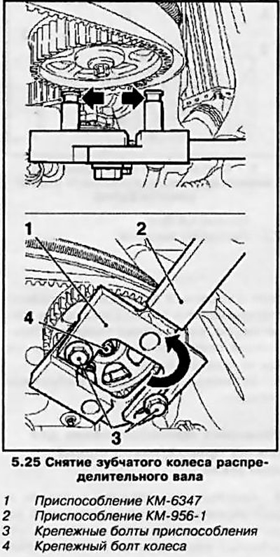
Note: The exhaust camshaft wheel is usually removed first.
26. Use the help of an assistant to keep the wheel from turning with the help of the installed device, unscrew the wheel mounting bolt and remove the wheel. Remove tool from pulley.
27. Repeat the procedure to remove the second (on respective models) gear wheel.
Installation
28. Install the wheels alternately in their places - tighten the wheel mounting bolts by hand.
Note: The intake and exhaust camshaft gears are different on some models - be careful.
Then install fixture (see above) and while holding the wheels from turning, tighten the fixing bolts with the required force. When installing, the alignment marks of the wheel and camshaft must match - usually they are made in the form of guide pins or keys.
Visitor comments