
Attention: Operations to remove the cylinder head should only be carried out when the engine is cold (ambient temperature) engine!
Note: This section provides a detailed description of the procedure for removing the engine head only for engines of earlier releases and the most widely used models supplied to the Russian market. But sufficiently experienced auto mechanics will be able to independently remove the head of the block on other models using the materials of this and some other sections of this Chapter!
Z16XEP engine
1. Disconnect a wire from the negative plug of the storage battery.
2. Remove the air cleaner (see chapter 4).
3. Remove the ignition module (see Chapter 1, Section 22).
4. Remove the multirib belt (see Section 7).
5. Raise the car on a lift, drain the coolant (see chapter 3) and remove the right engine boot (see Section 5).
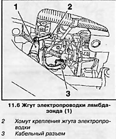
6. Disconnect the cable channels of the lambda probe (see resist. illustration).
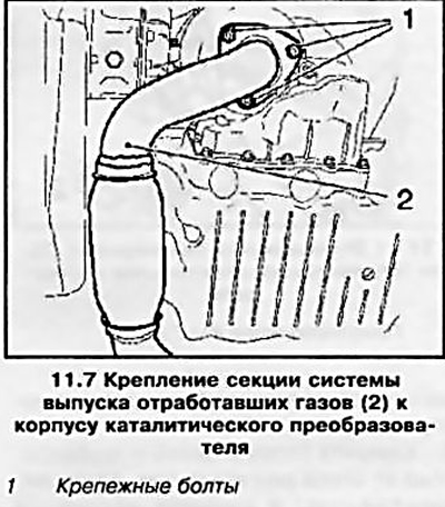
7. Disconnect the exhaust system section from the catalytic converter (see resist. illustration).
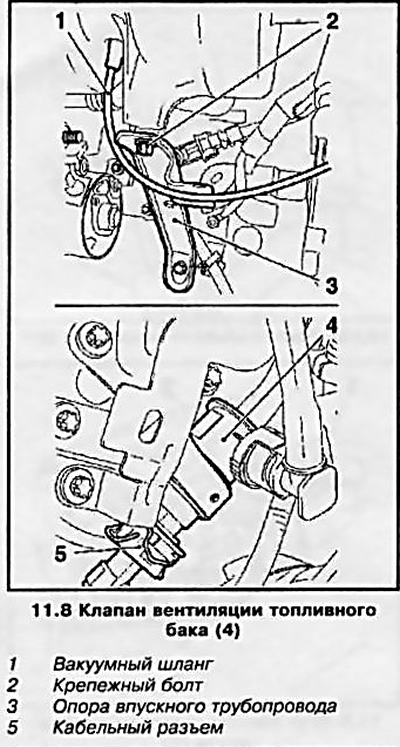
8. Remove the intake manifold support from the engine block (see resist. illustration) and remove the vacuum hose. Disconnect the wiring harness from the fuel tank vent valve.
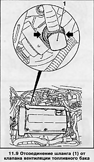
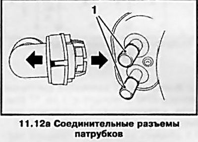
9. Remove the hose from the fuel tank vent valve by squeezing the retaining ring on the corrugated surfaces (see resist. illustration).
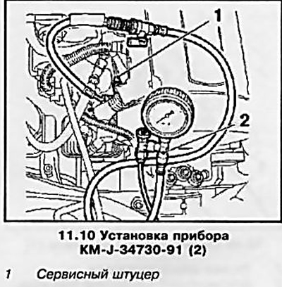
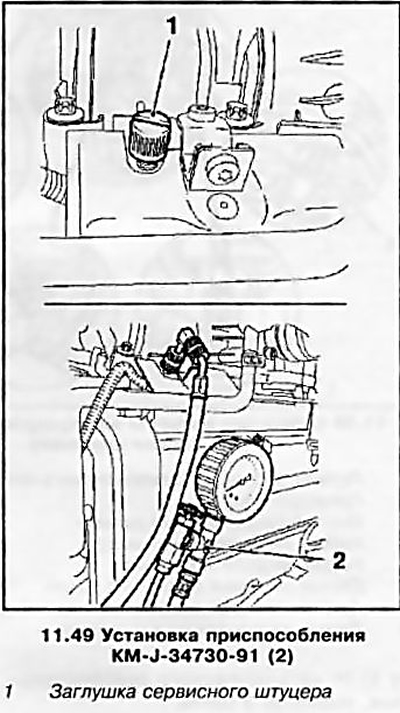
10. Relieve the pressure in the fuel system through the service fitting using a special tool KM-J-34730-91 (see resist. illustration).
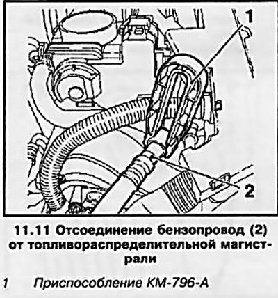
11. Disconnect the fuel line from the fuel distribution line using the KM-796-A tool (see resist. illustration).
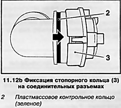
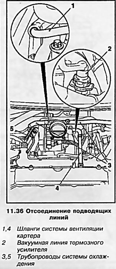
12. Disconnect the cooling system pipelines from the throttle body and from the interior heater - to disconnect the quick couplings, move the retaining rings back until they stop (see resist. illustrations).
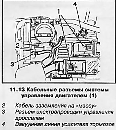
13. Disconnect the electrical wiring of the engine management system and the ground bus (see resist. illustration).
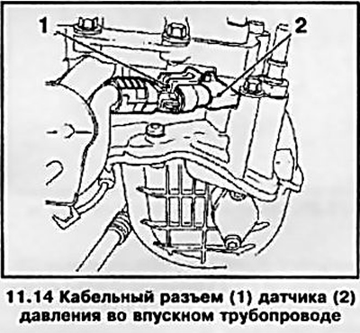
14. Disconnect the cable connector of the pressure sensor in the inlet pipeline (see resist. illustration).
15. Disunite a socket of electroconducting of the gauge of camshafts.
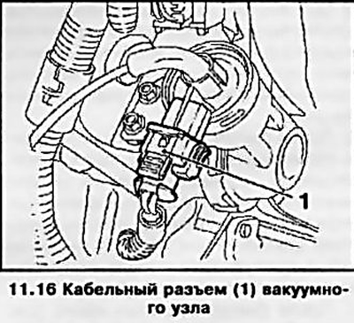
16. Disconnect the wiring connector of the vacuum unit of the PDA system (see resist. illustration).
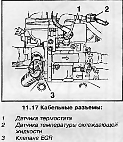
17. Disconnect the electrical wiring connectors of the thermostat sensors, coolant temperature and EGR valve (see resist. illustration).
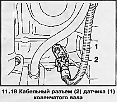
18. Disconnect the crankshaft sensor wiring connector (see resist. illustrations).
19. Disconnect the brake booster vacuum line and throttle control wiring connector (see illustration 11.13).
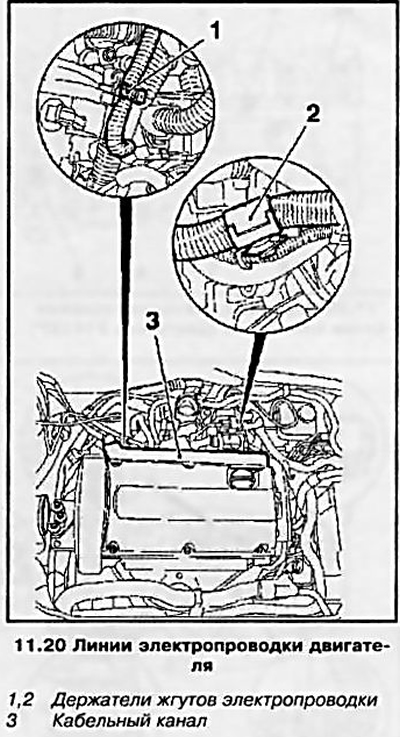
20. Disconnect wiring lines from engine (see resist. illustration).
21. Disconnect the crater ventilation hose from the cylinder head.
22. Remove the top timing cover (see Section 6).
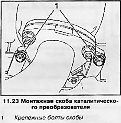
23. Raise the vehicle on a lift and disconnect the catalytic converter mounting bracket (see resist. illustration). Remove crankshaft pulley (see Section 5) and then remove the toothed belt (see Section 8).
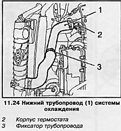
24. Disconnect the lower pipeline of the cooling system from the thermostat housing (see resist. illustration).
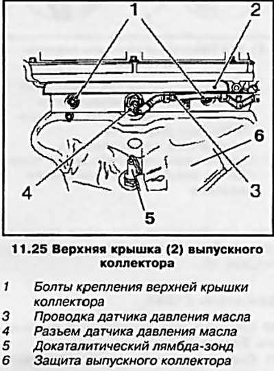
25. Remove the top cover of the exhaust manifold (see resist. illustration), for which disconnect the wiring of the oil pressure sensor in the engine head and unscrew the 2 fixing bolts. Remove the oil pressure sensor and pre-catalytic lambda probe. Remove the engine lifting eye, and then, unscrewing the 3 mounting bolts, remove the exhaust manifold protection.
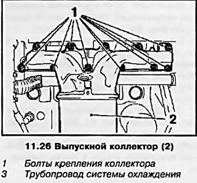
26. Turn out 11 fixing bolts and remove an exhaust manifold (see resist. illustration). Then turn out 5 bolts of fastening of the pipeline of the cooling system to the block of the engine and remove the pipeline.
27. Remove the cylinder head cover (see Section 10).
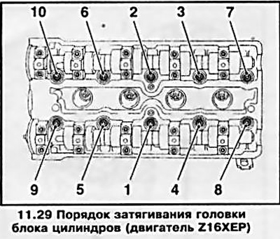
28. Release the head mounting bolts in the reverse order shown in Illustration 11.29 in two stages - at the first approach, loosen the bolts by 90°, and at the second - by 180°, then completely unscrew the bolts and remove the block head.
29. Installation is carried out in the reverse order of removal, while replacing all sealing gaskets of the removed components. Tighten threaded connections to the required torque (see specs). When installing the block head, use new fixing bolts. The tightening of the cylinder head bolts is carried out in the sequence indicated on the resist. illustrations in 5 stages: in the first approach, tighten the bolts using a torque wrench, and in subsequent approaches, using a special goniometric device. Features of installation of a cover of a head of the block of cylinders are resulted in Section 10.
Z18XE engine
30. Remove the multirib belt (see Section 7).
31. Remove the right engine boot (see Section 5).
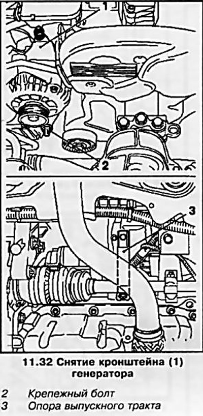
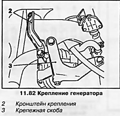
32. Turn out a bolt of fastening of the alternator and remove an arm (see resist. illustration).
33. Remove the right front wheel (see Introduction) and drain the coolant (see chapter 3). Disconnect the front exhaust pipe from the exhaust manifold by loosening the 3 fixing nuts.
34. Remove the support of the exhaust tract (see illustration 11.32) to the side, for which disconnect it from the intake manifold by unscrewing the bolt and loosening the bolt securing the support to the cylinder block.
35. Remove the multirib belt tensioner, remove the crankshaft pulley and install the right engine mount remover (see Section 5).
36. Disconnect the crankcase ventilation system hoses from the cylinder head cover and throttle, disconnect the cooling system pipeline from the intake manifold and cylinder head cover, disconnect the brake booster vacuum line from the intake manifold by squeezing the clamps (see resist. illustration). Disconnect the throttle cable connector.
37. Disconnect the cable connectors of the electrical wiring and other elements indicated on the resist. illustrations.
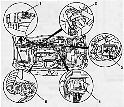
11.37a Electrical cable connectors
1 Fuel tank vent valve
2 Camshaft sensor
3 Switchgear solenoid valve
4 Lambda probe catalytic converter of exhaust gases
5 Coolant temperature sensor
38. Disconnect the cable channel (wiring harness in the housing) injectors from the engine. Relieve the pressure in the fuel system through the service fitting using a special tool KM-J-34730-91 (see illustration 11.10). Drain the fuel into a suitable container.
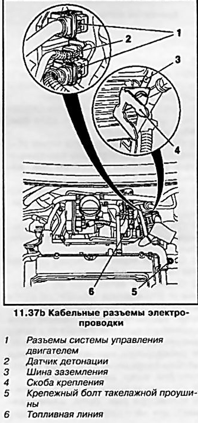
39. Disconnect the fuel line (see illustration 11.37b) and the wiring connector for the pre-catalytic lambda probe.
40. Disconnect the heater hose (see resist. illustration), and then disconnect the coolant pipe from the thermostat housing.
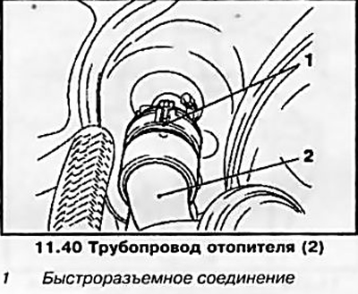
41. Remove the rear engine lashing eye and disconnect the intake manifold assembly by unscrewing the 7 mounting nuts (see resist. illustration).
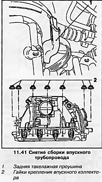
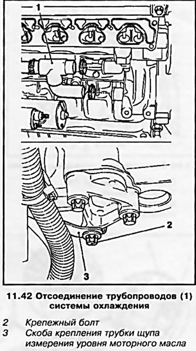
42. Disconnect the cooling system pipes from the water pump by removing the 2 fastening clamps (see resist. illustration). Disconnect the upper water pipe from the thermostat housing. Unfasten the dipstick tube for measuring the engine oil level by unscrewing the 2 mounting bolts, loosen the tube bracket bolt and move it to the side.
43. Remove the right engine mount and remove the toothed belt (see Section 8).
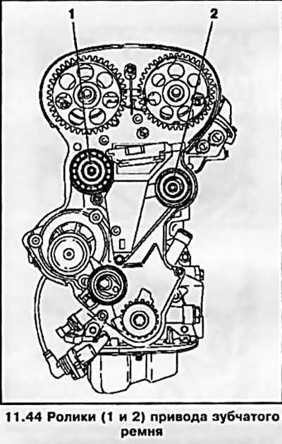
44. Remove the toothed belt drive rollers (see resist. illustration), remove the camshaft gears (see Section 5) and remove the right engine mount bracket from the cylinder block.
45. Remove the head cover, unscrew the mounting bolts and remove the cylinder head - the procedure and sequence for turning out / tightening the cylinder head bolts is the same as for the Z16XEP engine (see above).
46. Installation is carried out in the reverse order of removal, while replacing all sealing gaskets of the removed components. Tighten threaded connections to the required torque (see specs). When installing the block head, use new fixing bolts. Features of installing the head cover are given in Section 10.
Z14XEP engine
Withdrawal
47. Disconnect the wire from the negative terminal of the battery and remove the air cleaner (see chapter 4).
48. Disconnect the cable connector of the electrical wiring and pipelines of the cooling system from the throttle body (see resist. illustration).
49. Relieve the pressure in the fuel system through the service fitting using a special tool KM-J-34730-91 (see resist. illustration). Drain the fuel into a suitable container.
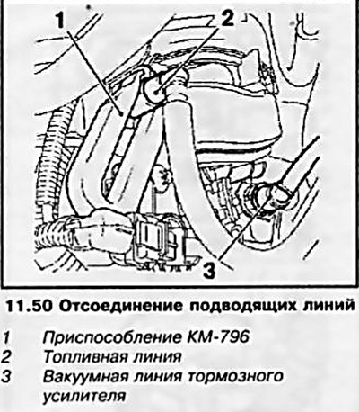
50. Disconnect the fuel line using the KM-796 tool and the brake booster vacuum line (see resist. illustration).
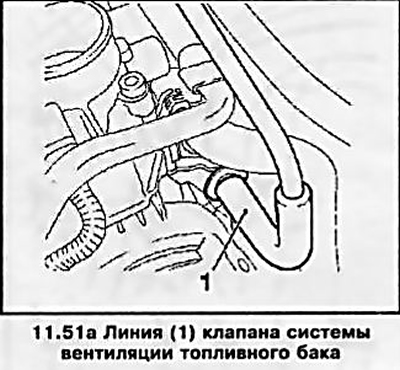
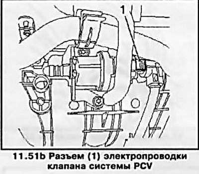
51. Disconnect the fuel tank vent valve line from the throttle body (see illustration 11.51a) and valve wiring connector (see illustration 11.51b).
52. Disconnect the exhaust pipe of the exhaust system (see chapter 4) from the catalytic converter by removing 3 bolts.
54. Drain the coolant (see chapter 3).
55. Disconnect the wiring harness connectors shown in Ref. illustrations.
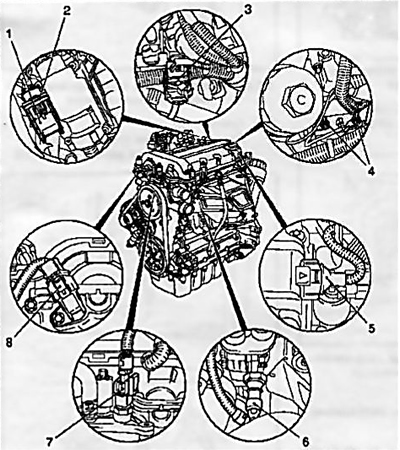
11.55 Cable connectors for electrical wiring of sensors and engine systems
1 Engine management connector
2 Fuse
3 Multifunction jack
4 Earthing cables to ground
5 Ignition module connector
6 Engine oil pressure sensor
7 Coolant temperature sensor
8 Camshaft sensor
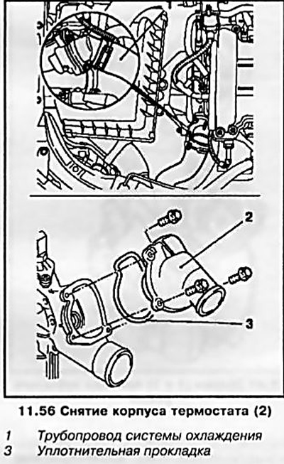
56. Disconnect the thermostat housing from the water pump by unscrewing 3 bolts and disconnect the cooling system pipeline from the radiator (see resist. illustration).
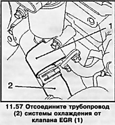
57. Disconnect the cooling system pipe from the EGR valve (see resist. illustration).
58. Unfasten the dipstick tube for measuring the engine oil level from the exhaust manifold protection by unscrewing the mounting bolt and remove the tube.
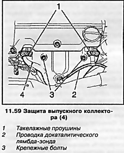
59. Remove the protection of the exhaust manifold, for which first disconnect the wiring of the pre-catalytic lambda probe and the lifting eyes (see resist. illustration).
60. Disconnect the exhaust manifold by loosening the 9 fixing nuts.
61. Remove the oil filter, to do this, first disconnect the filter cover and remove the filter element (see Chapter 1, Section 6), and then remove the oil filter housing (see resist. illustration).
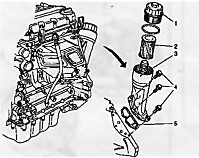
11.61 Removing the oil filter
1 filter cover
2 Replaceable filter element
3 Oil filter housing
4 Mounting bolts
5 Gasket
62. Remove the multirib belt (see Section 7).
63. Remove the water pump pulley by removing the 3 mounting bolts.
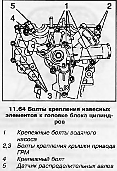
64. Remove the mounting bolts that secure the hinged elements of the power plant to the cylinder head (see resist. illustration).
65. Disconnect the crankcase ventilation system hoses from the cylinder head cover and remove the ignition module (see Chapter 1, Section 22).
66. Turn out 13 fixing bolts and remove a cover of a head of the block of cylinders.
67. Bring the piston of the first cylinder to the TDC position of the end of the compression stroke (see Section 6).
68. Remove the camshaft drive sprockets (see Section 8) and put them together with the chain in the timing case.
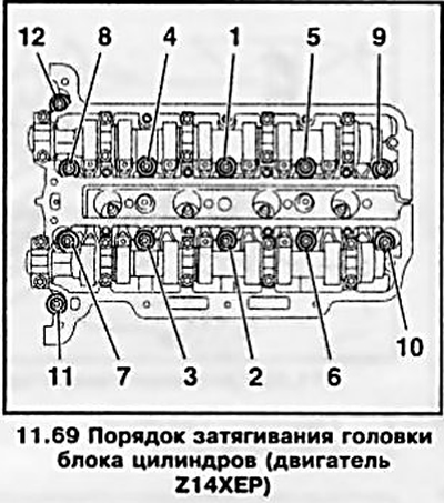
69. Loosen the head mounting bolts in the reverse order to that shown in Ref. illustrations in 2 stages - in the first approach, loosen the bolts by 90°, and in the second - by 180°, then completely unscrew the bolts.
70. Using the help of an assistant, remove the cylinder head - while the chain tensioner should move along its guide. The removed head should be laid on a wooden surface.
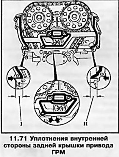
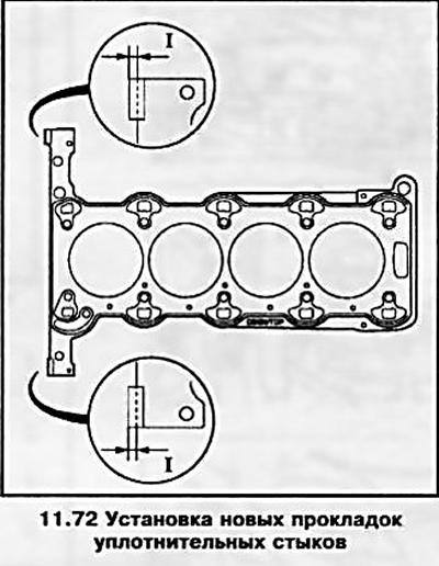
71. Remove the remaining sealant from the surfaces on the inside of the rear timing cover and the upper surface of the cylinder block, carefully pry the gaskets at the points indicated on the resistance. illustrations with arrows, and delete them.
Installation
72. Install new gaskets and cut off protruding edges (I) from the timing case (see resist. illustration).
73. Before installing a new head gasket, apply a bead of sealant (gray color) about 2 mm thick at the corners of the junction of the cylinder block with the timing case (see resist. illustration).
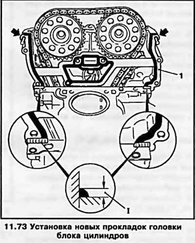
Attention: Installation of the head must be completed no later than 10 minutes after applying the sealant!
Install a new head gasket marked «TOR» upwards and press in places where the sealant is to be applied. Insert the timing cover mounting bolts (see ibid), put the gaskets on the vertical surface of the timing case cover and press the gaskets down at the places where the sealant is applied.
74. With the help of an assistant, install the block head - put the chain tensioner on the guide and using the KM-955-1 tool (see illustration 8.71) fix it.
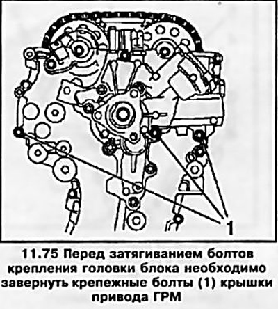
75. Secure the head by tightening the new head mounting bolts a few turns, tap the head using a rubber mallet towards the timing case and tighten the 3 drive cover mounting bolts (see resist. illustration).
76. Tightening the cylinder head bolts is carried out in the sequence shown in illustration 11.69, in 4 steps (see specs): in the first approach, tighten the bolts using a torque wrench, and in subsequent approaches, using a special protractor device.
77. Remove the previously installed 3 timing cover mounting bolts, install and tighten the removed water pump mounting bolts and then all the timing cover mounting bolts.
78. Installation of other components is carried out in the reverse order of removal, while replacing all sealing gaskets of the removed components. After installing the drive sprockets, adjust the valve timing (see Section 6). Features of installing the cylinder head cover are given in the same place.
Z20LE engines (L/R/H)
79. Disconnect the wire from the negative terminal of the battery and remove the air cleaner with air pipes (see chapter 4).
80. Remove the multirib belt (see Section 7).
81. Remove the ignition module (see Chapter 1, Section 22).
82. Disconnect the mounting bracket from the intake manifold and generator and the mounting bracket from the generator, intake manifold and cooling flange (see resist. illustration). Move the generator back.
83. Hang the car, remove the right front wheel (see Introduction), drain the coolant (see chapter 3).
84. Disconnect the vacuum reservoir bracket from the intake manifold and remove the front pipe of the exhaust system.
85. Remove the right engine boot (see Section 5) and multirib belt (see Section 7). Turn out bolts of fastening and remove a tension roller of a multirib belt.
86. Remove the crankshaft pulley and install the right engine mount remover (see Section 5).
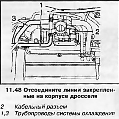
87. Disconnect all lines from the throttle body (see resist. illustration) and remove the throttle body.
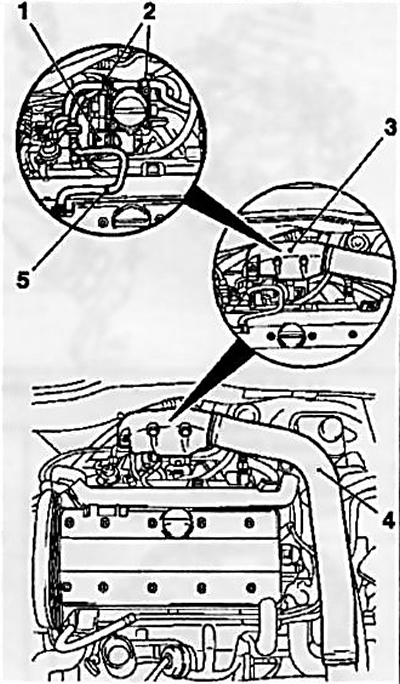
11.87 Disconnect the lines from the throttle body
1 Wiring connector
2 Fastening of a branch pipe of the cooling system
3 Air intake deflector
4 Air suction pipe
5 Crankcase ventilation hose
88. Disconnect the brake booster vacuum line from the intake manifold.
89. Relieve the pressure in the fuel system through the service fitting using a special tool KM-J-34730-91 (see chapter 4). Drain the fuel into a suitable container.
90. Disconnect the indicated on the resist. illustrations of fuel lines and hoses of the cooling system.
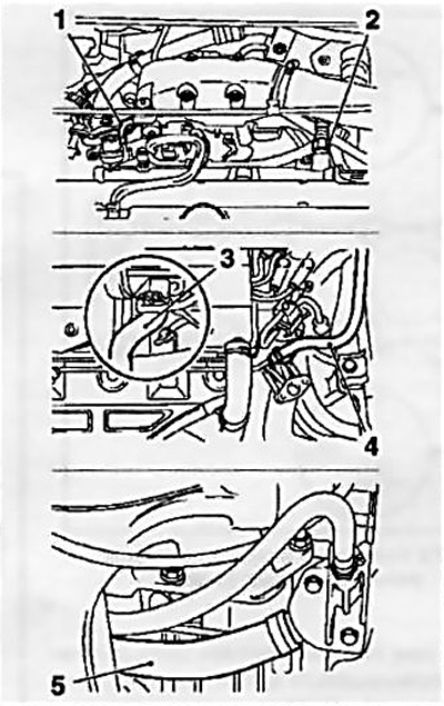
11.90 Disconnect the following lines and pipes:
1, 2 fuel lines from the fuel pressure regulator
3 pipeline of the cooling system from the tempostat housing
4 hose from the cooling system pipeline
5 pipeline from cooling flange
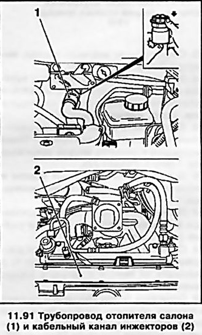
91. Remove the top cover of the timing drive, disconnect the interior heater hoses and all connectors of the cable channel of the injectors (see resist. illustration). Disconnect the cable duct from the injectors and set it aside.
92. Remove the timing belt (see Section 8).
93. Remove the camshafts (see Section 10).
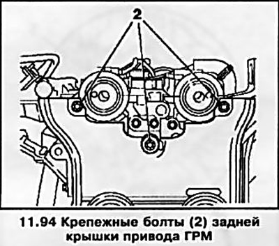
94. Unscrew the mounting bolts of the rear timing cover from the head of the block (see resist. illustration).
95. Using the KM-2355 tool, loosen the head mounting bolts in turn in several approaches in the reverse order shown in Illustration 11.95, releasing the bolts 1-0.5 turns per approach, then completely unscrew the bolts and remove the block head.
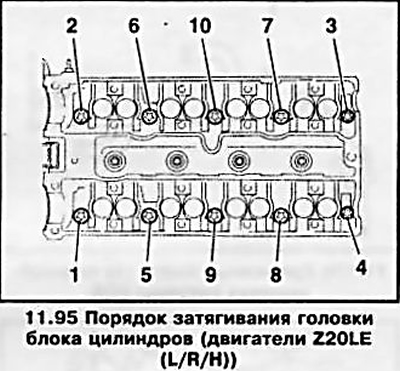
96. Installation is carried out in the reverse order of removal, while replacing all gaskets of the removed components - do not forget to clean the surfaces before installation. A new head gasket must be installed with the marking «TOR» up. Tighten threaded connections to the required torque (see specs). When installing the block head, use new fixing bolts. The cylinder head bolts are tightened in the sequence shown in illustration 11.95 in 5 steps: in the first approach, tighten the bolts using a torque wrench, and in subsequent approaches, using a special goniometric device. Features of installation of a cover of a head of the block of cylinders are resulted in Section 10.
Z22YH engine
97. The tightening of the cylinder head bolts is carried out in the sequence indicated on the resist. illustrations from 1 to 10 in 4 steps: in the first approach, tighten the bolts using a torque wrench, and in subsequent approaches, using a special goniometric device (see specs). New bolts must be used.
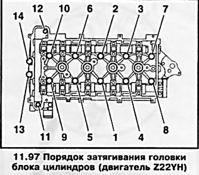
98. Insert 4 bolts into the timing case, having previously lubricated their threads with a fixing compound, and tighten in sequence from 11 to 14 with a force of 35 Nm.
Note: Before installing the bolts, carefully clean the threads of the holes from the remnants of the old compound.
Z17DTL/H engines
Withdrawal
99. Operations on removal of a head of the block of the engine on the models equipped with the K/V system are described below.
100. Before performing work, it is necessary to disconnect the battery, remove the refrigerant from the A/C system using special service equipment (contact the service station of the Opel campaign) and drain the coolant (see chapter 3).
101. Remove the engine cover (see section 2), remove the air cleaner (see chapter 4) remove the multirib belt (see Section 7), remove the engine crankcase protection (see Section 5), drain the engine oil from the crankcase (see Chapter 1, Section 6).
102. Remove the compressor of the K / V system and the timing case (see Section 10), while completing all the work to remove the toothed belt (see Section 8) and nozzles (see chapter 4).
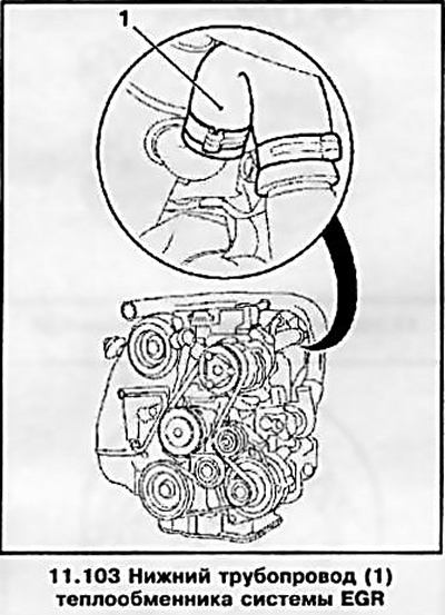
103. Disconnect the lower pipeline of the cooling system from the heat exchanger of the exhaust gas recirculation system (EGR) (see resist. illustration).
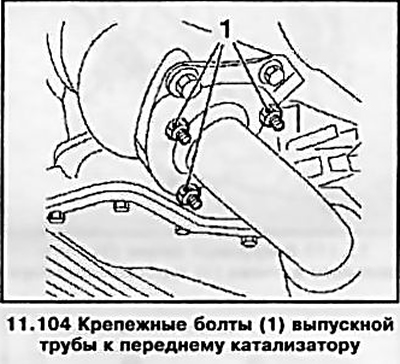
104. Disconnect the front end of the exhaust pipe from the front catalyst by unscrewing the 3 mounting bolts (see resist. illustration).
105. After removing the 2 bolts, disconnect the dipstick tube for measuring the engine oil level from the top of the oil pan by removing the 2 bolts.
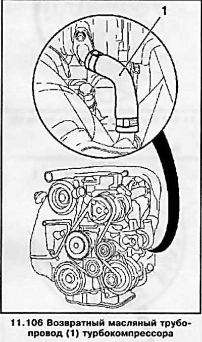
106. Disconnect the return oil pipe from the turbocharger (see resist. illustration).
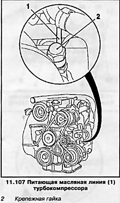
107. Disconnect the turbocharger oil supply line from the engine block (see resist. illustration).
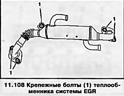
108. Remove the heat exchanger of the EGR system (see resist. illustration).
109. Disconnect the wiring connector from the EGR system regulator, disconnect the cooling system pipeline from the EGR recirculator housing and remove the housing (see resist. illustrations).
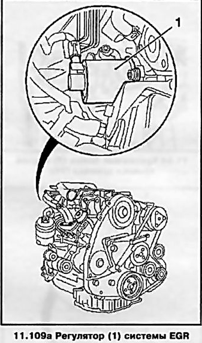
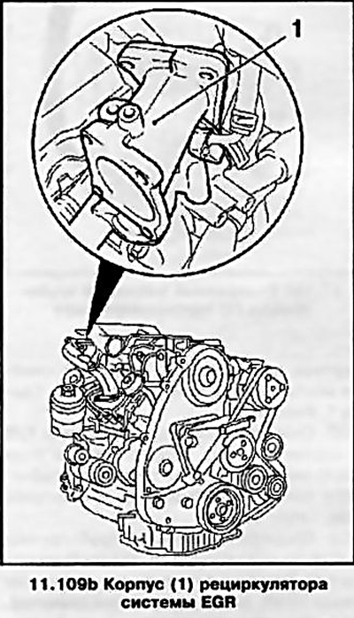
Note: The housing mounting bolts are of different lengths - remember or mark the places of their installation.
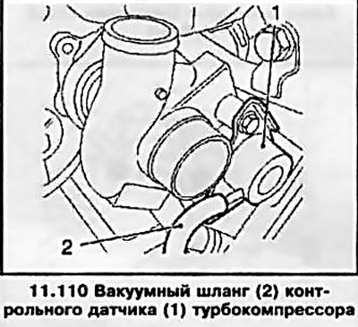
110. Disconnect the vacuum hose from the turbocharger control sensor (see resist. illustration).
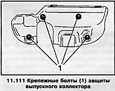
111. Remove the exhaust manifold protection by removing 4 bolts (see resist. illustration).
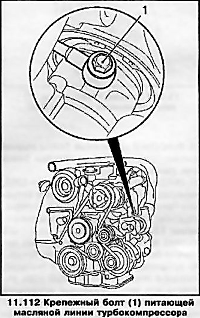
112. Disconnect the oil supply line from the turbocharger housing (see resist. illustration).
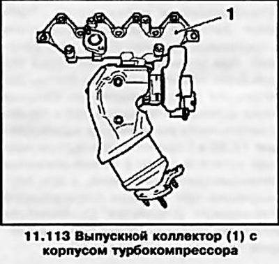
113. Remove the exhaust manifold with the turbocharger (see resist. illustration), by removing 2 bolts and 7 fixing nuts.
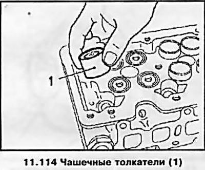
114. Remove 16 cup pushers from the head (see resist. illustration) - remember the order of their installation during assembly, they must be strictly in their places.
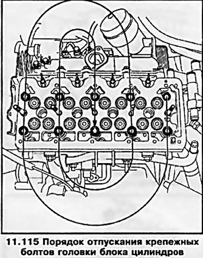
115. Turn out fixing bolts of a head of the block of cylinders alternately in several steps, releasing them on 1-0.5 turns for the approach, in the order specified on resist. illustrations. Remove the head.
Examination
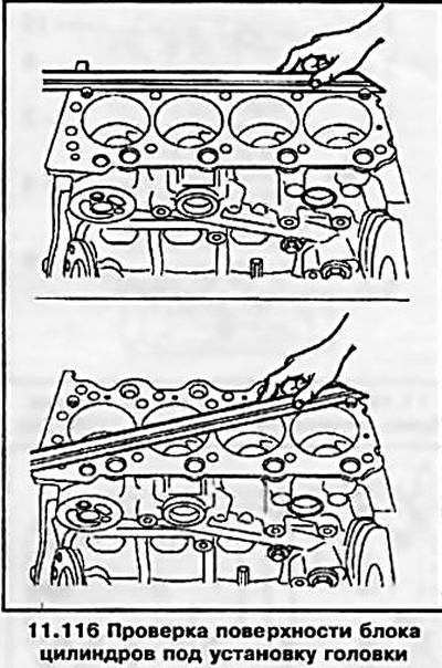
116. After removing the head, it is necessary to clean the mating surfaces of the head and the engine block and check them for surface deformation using a fixture with a flat, straight edge (see resist. illustration).
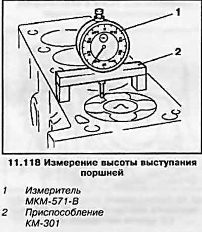
117. For this engine, the thickness of the new cylinder head gasket is of particular importance. To obtain the optimal volume of the combustion chamber, the engine pistons protrude slightly on the surface of the block at their TDC. To ensure that the piston and timing valves do not touch during operation, it is necessary to provide an appropriate clearance.
118. To measure the height of the protrusion of the piston above the surface of the block, it is necessary to install devices on the surface of the block (see resist. illustration) and expose «ABOUT» on the scale of the plunger-type meter at the moment when the meter probe is in contact with the surface of the block.
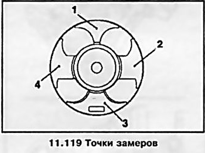
119. Measure the protrusion height of all pistons one by one, measuring at two points on each piston (see resist. illustration) - for measurement it is necessary to select points (1) And (2) or another pair (3) And (4). When measuring, rotate the crankshaft smoothly to determine the highest piston lift point. At the end of the measurement, turn the crankshaft 60°counterclockwise.
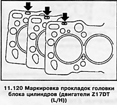
120. Determine the thickness of the new gasket according to the data in the table (see specs). Appropriate labeling (holes) applied to pads (see resist. illustration).
Installation
121. Installation is carried out in the reverse order of removal, while replacing all sealing gaskets of the removed components. Tighten threaded connections to the required torque (see specs). The cylinder head bolts are tightened in 3 steps: in the first approach, tighten the bolts using a torque wrench, and in the subsequent ones, using a special goniometric device. When installing the block head, use new fixing bolts. The bolt tightening order is the same as for the Z14XEP engine (see illustration 11.69).
Note: Only 1 to 10. Adjust the valve timing (see Section 9).
Z13DTH engine
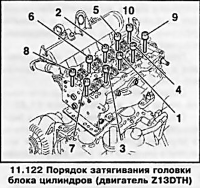
122. The tightening of the cylinder head bolts is carried out in the sequence indicated on the resist. illustrations 1 to 10, in 3 steps (see specs): in the first approach, tighten the bolts using a torque wrench, and in subsequent approaches, using a special protractor device. New bolts must be used.
Z19DT engines (H)
123. The tightening of the cylinder head bolts is carried out in the sequence indicated on the resist. illustrations in 5 steps (see specs): on the first and second approaches, tighten the bolts using a torque wrench, and on subsequent approaches, using a special goniometric device.
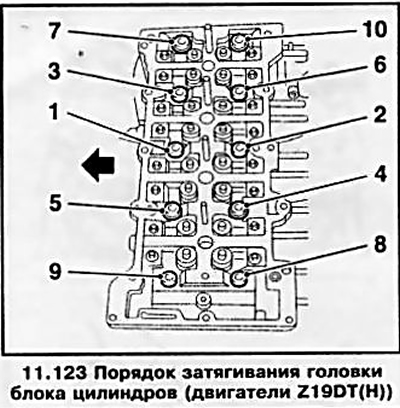
Note: The illustration shows the Z19DTH engine.
Visitor comments