
Attention: In the electronic ignition system, a very high voltage is generated! Be careful, observe all necessary precautions when servicing any system components, including not only the main (ignition module), but also related, such as spark plug connectors, tachometer and other equipment!
1. The correct functioning of the spark plugs is largely determined by the efficiency of the engine output. It is important that the spark plugs of the exact type specified by the manufacturer are installed on the engine (see specs). Attempts «improve» engine by installing more expensive and at first glance the best candles are likely to lead to the opposite result. On a serviceable engine, the need for unscheduled maintenance of spark plugs is extremely rare; you should not unscrew the spark plugs unnecessarily to check. To avoid accidental damage to the electrodes, do not service or clean the spark plugs without the use of special equipment.
2. To replace spark plugs, a special spark plug head is required (16 mm) complete with extension, universal joint and torque wrench (see resist. illustration). Using a torque wrench will allow you to achieve the correct tightening torque for the candles.
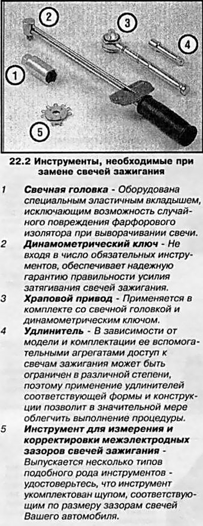
Attention: Use a spark plug wrench with an elastic insert to prevent damage to the spark plug insulator!
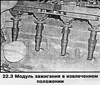
3. All models covered in this manual are equipped with an ignition module. It is installed between the camshaft housings, directly above the spark plugs (see resist. illustration).
Attention: All work on the replacement of the candle should be carried out only on a cold engine (engine temperature can be touched by hand) - otherwise, when removing the candles on a hot engine, you can damage the internal thread of the hole for installing candles on the cylinder head.
4. Before removing the module on 1.8 l models, remove the engine cover (see chapter 2), and on models with a displacement of 1.6 l, separate the cable channel from the cylinder head. Disconnect the electrical wiring from the ignition module and remove the module cover in the direction indicated by the arrow (see resist. illustration).
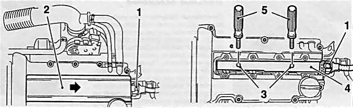
22.4 Removing the ignition module cover
1 Electrical plug
2 Ignition module cover
3 threaded holes for the installation of handles
4 Ignition module housing
5 Special handles
Note: Depending on the model, the direction of the arrow may be different.
Unscrew the mounting screws, screw special handles into the central threaded holes of the module, and if they are not available, a pair of long bolts of a suitable diameter with the appropriate thread pitch, and remove the module from the block head.
Note: These handles are also used to prevent hand burns when removing the ignition module on a hot engine.
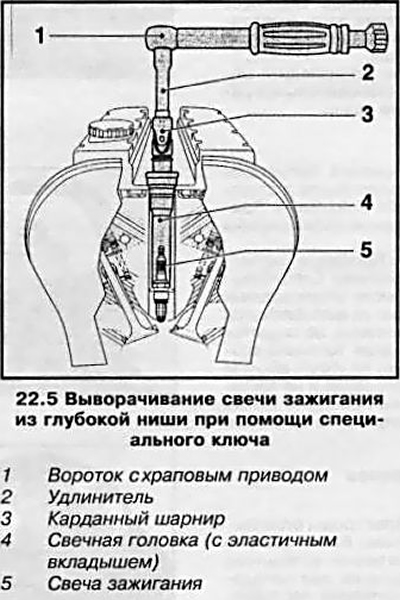
5. Spark plugs are deeply recessed into candle niches, so you will need a key drive extension to turn them out (see resist. illustration). Putting the head on the candle, connect the drive and, gently turning the collar counterclockwise, unscrew the candle.
6. Check the inside out candle against state map, which will allow a qualitative assessment of the general condition of the engine.
7. Checking the condition of the spark plugs gives a good indication of the condition of the engine. If there are no traces of any deposits on the insulator of the central electrode, this indicates a re-leaning of the air-fuel mixture, or that it is being used excessively «hot» candle (heat dissipation from the insulator to the housing «hot» candlelight is much less intense than on «cold»),
8. The presence of black deposits on the electrodes indicates a re-enrichment of the mixture, and if the deposits still have an oily consistency, you should also consider a more detailed assessment of the degree of wear of the internal components of the engine.
9. A coating of a golden or gray-brown hue on the insulator confirms the good condition of the engine and the correct layout of the air-fuel mixture.
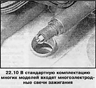
10. Modern engines use different types of spark plugs. Multi-electrode spark plugs are widely used (see resist. illustration), which have increased wear resistance and reliability. The installation of interelectrode gaps on such candles is carried out at the factory and, as a rule, does not need any adjustments. If necessary, the installation of interelectrode gaps should be carried out in accordance with the instructions of the candle manufacturers.
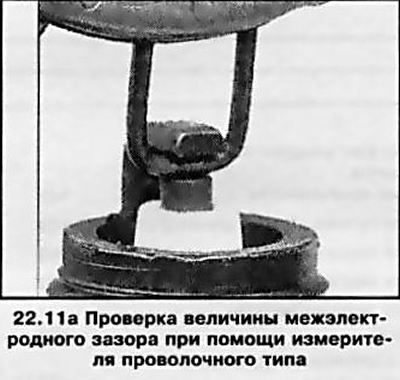
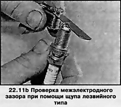
11. Measurement of the interelectrode gap is carried out using a special wire-type probe (see resist. illustration 22.11a). When adjusting, only the side electrodes should be bent - attempts to deform the central electrode are fraught with irreversible damage to the insulator. If a blade-type feeler gauge is used to measure the spark plug gap, the gap can be considered correctly adjusted when the feeler blade is passed into it with slight resistance (see resist. illustration 22.11b).
12. Before installing the candle, make sure that the threads on the body and the outer surface of the candle are well cleaned.
13. If, during inspection of the candle, damage to the threaded connection is found, the candle must be replaced, and if the thread in the head of the block is damaged, it is necessary to cut a new thread with a special tool without removing the head for a special adapter, which is screwed onto a standard candle.
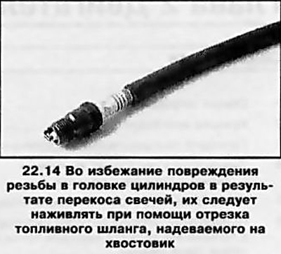
14. Thread one of the new spark plugs into the appropriate hole in the engine by hand. After making sure that the candle is not skewed in the thread, tighten it with the required force (see specs). To facilitate the procedure for baiting a candle, pull a piece of flexible fuel hose onto its shank (see resist. illustration) in order to exclude the possibility of thread breakage, since at the slightest biting, the hose will simply begin to turn. Proceeding in a similar manner, install all the remaining candles.
15. Install the ignition module and tighten its fasteners with the required force (8 Nm).
Note: On engines with a displacement of 1.6 liters, the 4 gaskets of the ignition module must also be replaced.
Replace the cover and connect the plug connector of the module. Depending on engine model (see paragraph 4) install the cable channel on the block head and install the engine cover.
Visitor comments