
Note. Before the test procedure, warm up the engine to operating temperature (oil temperature - 80°C).
Removing
open the hood
Remove the air filter housing.
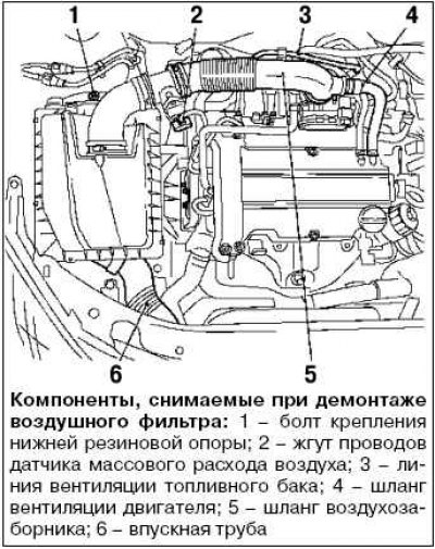
Disconnect the mass air flow sensor harness.
Disconnect the fuel tank vent line.
Disconnect the engine ventilation hose from the air intake hose.
After removing the clamp, disconnect the air intake hose from the throttle pipe.
After removing the clamp, disconnect the air filter housing.
Loosen the bottom rubber mounting bolt and remove it.
Disconnect the intake pipe.
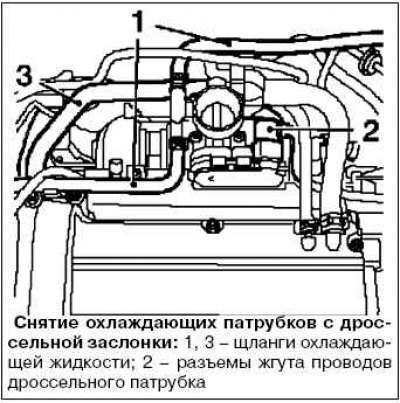
Disconnect the throttle body harness connectors.
Disconnect the coolant hoses from the throttle body.
Place a drain container underneath.
Remove 2 clamps.
Disconnect the coolant hose.
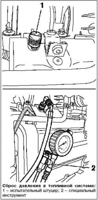
Relieve the fuel pressure using the special tool KM-J-34730-91 through the test nipple by unscrewing the protective cap of the test nipple.
Collect escaping fuel in a suitable container.
Comply with safety regulations and local laws
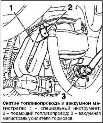
Disconnect the fuel supply line from the fuel rail using the KM 796 special tool.
Disconnect the quick coupler.
Disconnect the brake booster vacuum line from the intake manifold.
Disconnect the quick coupler.
Disconnect the fuel tank vent valve line from the intake manifold.
Disconnect the fuel tank vent valve harness connector.
Disconnect the front exhaust pipe from the catalytic converter by removing the 3 mounting nuts.
Place a drain container underneath
Connect a suitable hose to the drain fitting.
Loosen the coolant drain screw.
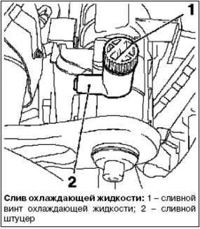
Drain the coolant.
Tighten the coolant drain screw.
Shutdown of power supply and engine control systems
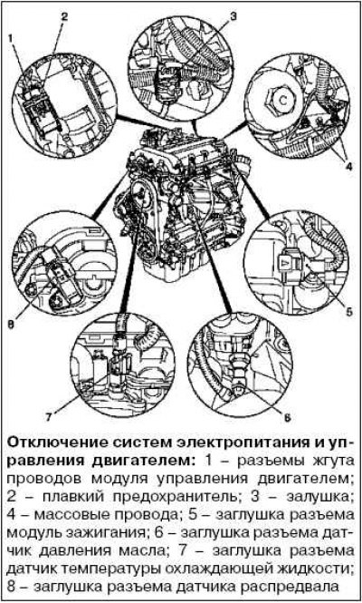
Disconnect the engine control module harness connectors.
Disconnect the fuse.
Disconnect the 2 ground wires by unscrewing the 2 fastening nuts.
Disconnect the 6 engine wiring harness plugs: plug, ignition module, oil pressure sensor, coolant temperature sensor, camshaft sensor.
Release the wiring harness.
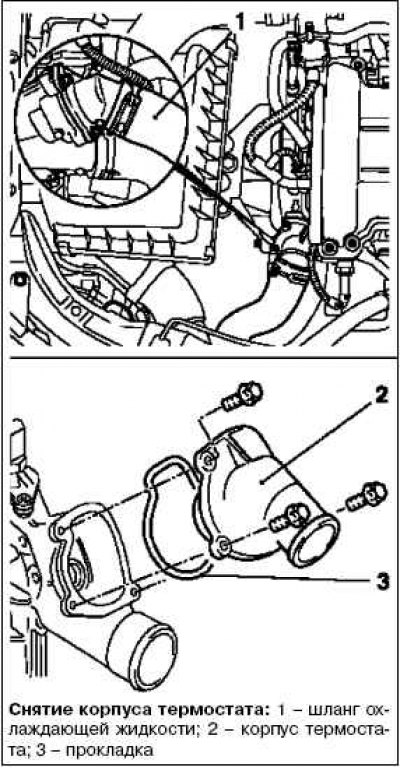
Disconnect the thermostat housing from the coolant pump by unscrewing the 3 mounting bolts.
Remove the gasket.
Disconnect the coolant hose from the radiator.
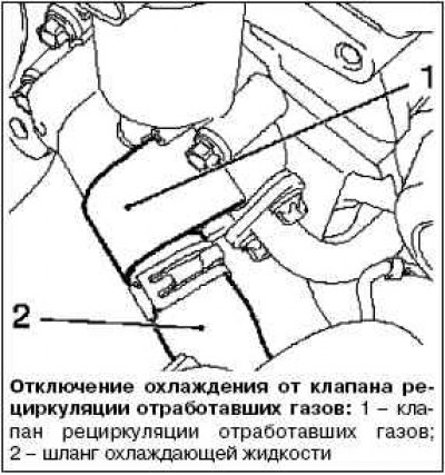
Disconnect the coolant hose from the EGR valve.
Loosen clamp.
Disconnect the oxygen concentration sensor harness connector.
Remove the bracket cover.
Disconnect the wiring harness from the bracket.
Remove the engine lifting lugs by removing the 2 mounting bolts.
Unscrew the heat shield.
Remove 2 bolts.
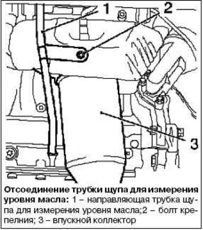
Remove the oil dipstick guide tube.
Disconnect from exhaust manifold.
Loosen the bolt.
Remove the exhaust manifold by unscrewing the 9 mounting bolts.
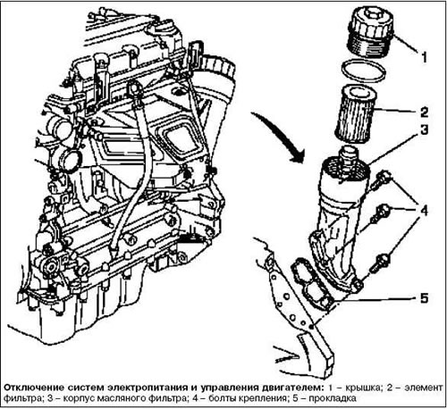
Removing the oil filter
Disconnect the cover from the oil filter housing.
Remove the oil filter element.
Disconnect the oil filter housing from the cylinder block by unscrewing the 3 mounting bolts.
Remove the gasket.
Remove poly V-belt.
Mark the direction of rotation.
Turn the poly V-belt tensioner clockwise using tool KM 6131.
Install the KM-955-2 tool.
Loosen the V-ribbed belt tensioner.
Disconnect the water pump pulley from the water pump by removing the 3 mounting bolts.
Remove the timing housing.
Remove 4 coolant pump mounting bolts.
Remove the 5 bolts securing the timing housing.
Disconnect the camshaft sensor from the timing mechanism housing by unscrewing the mounting bolt.
Disconnect the engine vent hose from the cylinder head cover.
Removing the ignition module
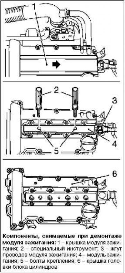
Remove the ignition module wiring harness.
Remove the ignition module cover from the cylinder head cover in the direction of the arrow
Loosen the two fixing screws.
Separate the ignition module from the spark plugs using the KM 6009 special tool.
Disconnect the cylinder head cover from the cylinder head by unscrewing the 13 mounting bolts.
Remove the cylinder block base cap.
Lower the car.
Set the piston of the first cylinder to the TDC position (ignition)
Install the special tool KM 952. Smoothly rotate the crankshaft until the special tool KM 952 reaches the stop.
The mark on the crankshaft pulley must align with the protrusion on the timing case.
Remove the guide from the cylinder head by unscrewing the 2 mounting bolts.
Remove the camshaft gears by unscrewing the 2 mounting bolts.
Hold the camshaft hex with an open wrench.
Place the camshaft sprockets on the same side as the chain in the timing case.
Removing the cylinder head
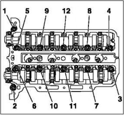
Turn away bolts of fastening of a head of the block of cylinders in the order shown in drawing.
Loosen 12 bolts by 90°.
Loosen 12 bolts by 180°.
Remove the cylinder head
Insert the chain tensioner behind the tension bar.
Install the cylinder head on the bars.
Remove the cylinder head gasket.
Disconnect the timing case gasket.
Cut off the sealing lips of the elastomer (size II) camshaft housing gaskets from inside to outside with a sharp knife and make flush with the cylinder block
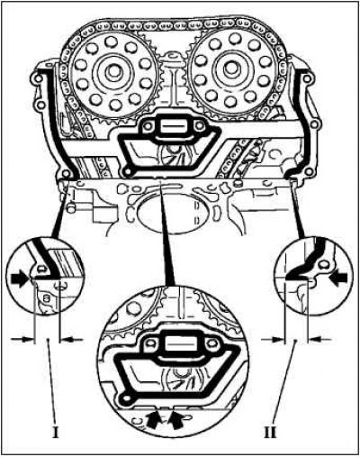
Gently bend the gasket at the fold points (arrows).
Remove gasket residue and clean sealing surfaces
Note. Ensure that any remaining elastomer sealing lip is removed from the space between the timing case and cylinder block and from the timing case.
Check the cylinder head and cylinder block for flatness.
When checking or repairing the cylinder head, disconnect all external components from the cylinder.
Install the cylinder head gasket.
Cut off the protruding parts of the elastomer (size I) from the gas distribution mechanism.
Installation
Bead silicone sealant (gray) on the timing case/cylinder block approx. 2 mm thick (size I).
Note. The cylinder head must be installed within 10 minutes after applying silicon (gray) sealant and installation of bolts of the gas distribution mechanism housing.
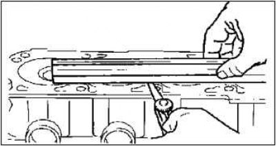
Install a new cylinder head gasket to the cylinder block.
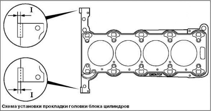
The TOP marking must be on top.
Press the gasket in the silicon application area (gray) sealant.
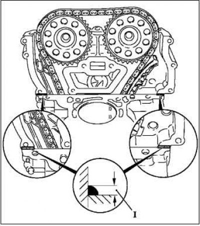
Install the top gasket of the timing case.
Install 2 (arrows) valve body bolts.
Install a new gasket on the timing case.
Fasten with screws.
Press the gasket in the silicon application area (gray) sealant.
Bead silicone sealant (gray) on the timing case / cylinder block with a thickness of approximately 2 mm (size I).
Installing the cylinder head
Insert special tool KM-955-1 through the hole in the timing case.
Insert the chain tensioner over the tension bar.
Install the pin into the guide.
Fasten the cylinder head.
Tighten the new cylinder head bolts a few turns.
Install the timing housing.
Note. Adjust the position of the cylinder head by tapping lightly with a rubber mallet in the direction of the timing case.
Tighten 3 bolts to 8 Nm.
Tighten the 12 cylinder head bolts to 25 Nm, tighten +60°+60°+60°.
Pay attention to the correct tightening sequence.
The rest of the components are installed in the reverse order of removal.
Visitor comments