
Removing
Remove the distributors.
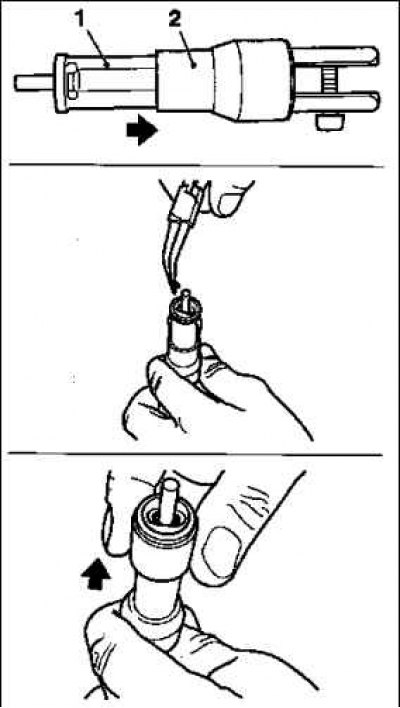
Remove spark plugs with special tool KM-194-E.
Raise the vehicle.
Remove the right engine mudguard.
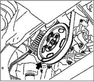
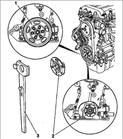
Make an alignment mark on the crankshaft pulley (arrow in the picture).
Note. Move 180°relative to the mark, TDC of cylinder No. 1.
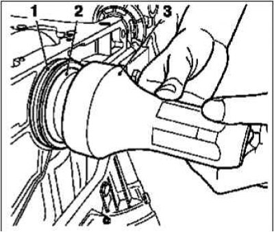
Prepare lever MKM-6086 for valve spring removal.
Adjust the supports with the special tool MKM-6086-6.
Center the pedestal heads with the pedestal legs and tighten.

Preparation of a special tool for removing the valve spring: 1 - support head; 2 - support legs; 3 - thrust part
Extend lever arm MKM-6086-7 with joint MKM-6086-8 and detachable head MKM-6086-10.
Install block kit MKM-6086-200.
Install thrust piece MKM-6086-200-10.
Attach the valve spring arm MKM-6086.
Attach supports MKM-6086-6.
Insert the block shaft into the supports.
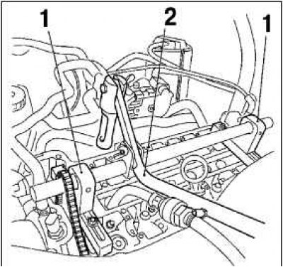
Installing the lever and supports for removing the valve spring: 1 - supports; 2 - lever
Note. Align the block shaft with the center of the spark plug hole
Tighten the 4 mounting bolts.
Install lever MKM-6086-7.
Note. The plug-in head must face the inlet side.
Attach the mounting shaft and tighten the 2 mounting bolts.
Install compressed air adapter.
Screw in the spark plug threads, cylinder #1.
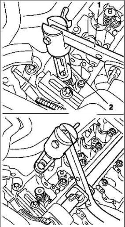
Valve spring compression procedure: 1 - lever; 2 - removable head
Apply compressed air to cylinder #1.
Remove the 2 cylinder #1 inlet valve springs.
Carefully push the valve springs down with the lever.
Note. The removable head must be placed vertically above the valve stem.
Attention! Observe correct installation.
Remove crackers and valve heads, valve springs.
Note. Do not use magnetic tools for this.
Replace valve stem seals.
Place a new valve stem seal on the valve stem.
Push it all the way in with KM 958.
Install intake valve springs, cylinder #1.
Install valve springs and valve heads.
Install the valve cotters into the block head.
Slide the plastic clamping sleeve in the direction of the lever arm attachment.
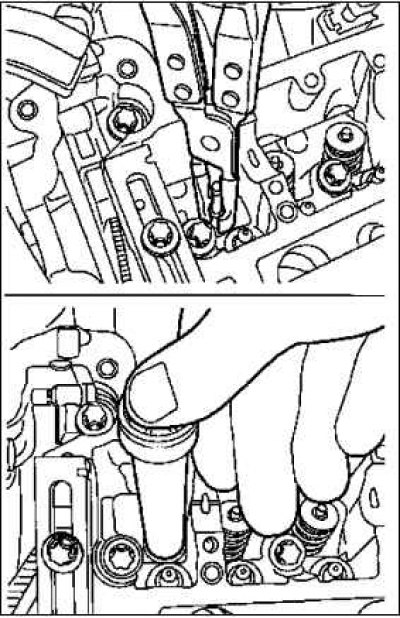
Installation of valve crackers in the head of the installation block: 1 - valve cracker; 2 - plastic clamping sleeve
Attention! Install the crackers with the tapered end towards the valve
Slide the plastic clamping sleeve towards the valve (arrow in the picture.
Attach the setting head to the lever.
Attention! The head must be positioned vertically above the valve stem. Rusks should enter the seat with a click.
Gently slide the valve springs down using the lever (arrow in the picture).
Attention! Do not make a 2nd attempt without making sure that both crackers are installed in the head of the block. Check the secure fit of the crackers. Ensure compressed air supply.
Installing valve crackers and valve springs: 1 - head; 2 - crackers
Move the lever and remove it.
Do the above procedure for all cylinders.
Shut off the compressed air supply line.
Remove the crankshaft lock.
Set the piston of cylinder No. 3 to the TDC position.
Pull the timing chain up.
Rotate the crankshaft evenly (180°).
Note. The mark on the crankshaft pulley must align with the protrusion on the timing case.
Block the crankshaft using the KM 952 special tool.
Reposition the compressed air adapter.
Shut off the compressed air supply line.
Unscrew adapter from spark plug thread, cylinder #4.
Screw in the spark plug threads, cylinder #2.
Apply compressed air to cylinder #2.
Replace valve stem seals, cylinder #2.
Reposition the compressed air adapter.
Shut off the compressed air supply line.
Unscrew the adapter from the spark plug thread, cylinder #2.
Screw in the spark plug threads, cylinder #3.
Apply compressed air to cylinder #3.
Replace valve stem seals, cylinder #3.
Shut off the compressed air supply line.
Disconnect the valve spring lever.
Remove compressed air adapter.
Release the crankshaft.
Place the shift lever in neutral position.
Disengage the parking brake system.
Raise the vehicle.
Block the crankshaft.
Pull the timing chain up.
Turn the crankshaft evenly until the special tool KM 952 stops.
Install special tool KM 952.
Lower the car.
Installation
Install spark plugs using special tool KM-194-E and tighten to 25 Nm.
Visually check the elements - camshafts, camshaft bearing cap, cylinder head, valve lifters, hydraulic valve lifters.
Install hydraulic lifters and valve lifters.
Removing the timing chain drive
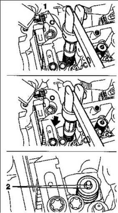
Loosen the camshaft pulley bolts.
Hold the camshafts by the hexagons.
Lock the chain tensioner.
Install special tool KM-955-1.
Slide the chain tensioner back and lock it with the special tool KM-955-1.
Remove the guide by unscrewing the 2 mounting bolts.
Remove the guide by unscrewing the 2 mounting bolts.
Remove the tension guide by unscrewing the mounting bolt.
Remove the timing chain, drive sprocket and timing case gasket.
Disconnect the crankshaft pulse sensor harness connector.
Remove the KM 952 special tool.
Remove the crankshaft pulse generator by unscrewing the mounting bolt.
Disconnect the base of the cylinder block from the cylinder block by unscrewing the 22 mounting bolts.
Remove the connecting rod bearing cap.
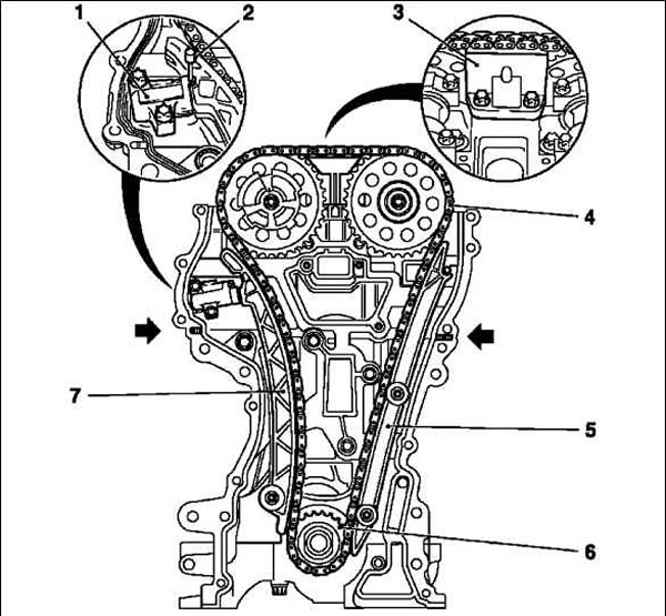
Removing the chain drive of the gas distribution mechanism: 1 - chain tensioner; 2 - special tool; 3 - guide; 4 – chain of a drive of the gas distribution mechanism; 5 - guide; 6 - asterisk; 7 - tension guide
Note. The contact surfaces of the connecting rods and connecting rod bearing caps are selected individually and therefore must not be rearranged or damaged. To avoid damage, do not place connecting rods and caps on the contact surfaces.
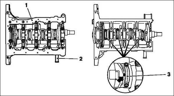
Removing the connecting rod cover: 1 - the base of the cylinder block; 2 - special tool; 3 – connecting rod bearing caps
Mark the connecting rod bearing caps.
Mark the sequence of cylinders.
Remove the 8 mounting bolts and remove the connecting rod cover.
Remove the crankshaft.
Disconnect the cylinder block base.
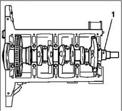
Removing the crankshaft: 1 - crankshaft
Note. Separate the base evenly with a mounting spatula.
Remove 22 bolts.
Remove the crankshaft rear oil seal.
Remove crankshaft and place on wooden blocks.
Remove the crankshaft bearing clamps.
Note. Follow the correct sequence
Remove the connecting rod bearing shells and mark them in the correct sequence.
Check all elements for wear and replace if necessary.
Checking the crankshaft
Check the ovality of the crankshaft. Check the axial free play of the crankshaft.
Disconnect the crankshaft pulse sensor disc by unscrewing the 3 mounting bolts.
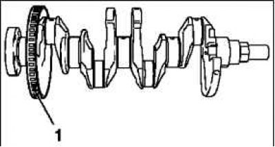
Crankshaft impulse sensor disk: 1 - disk
Installation
Attach the crankshaft pulse sensor disc and tighten the 3 mounting bolts to 15 Nm.
Install the crankshaft bearing shells into the cylinder block and into the base of the cylinder block.
Coat them with engine oil.
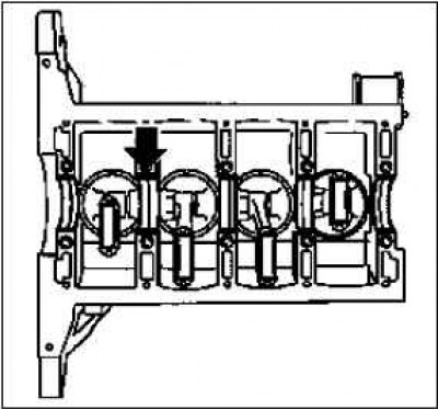
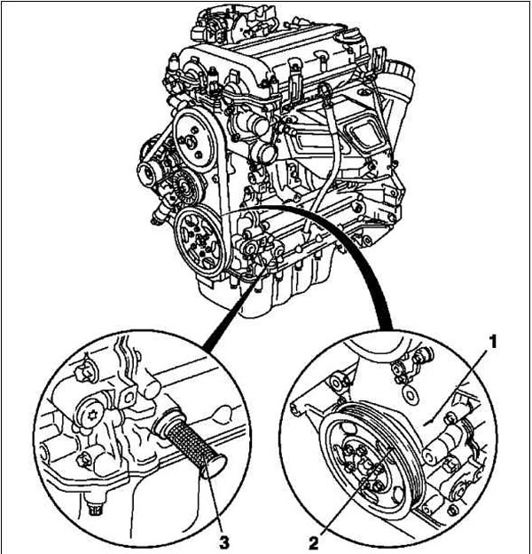
Mark the position of the thrust bearings (arrow in the picture).
Install the connecting rod bearing shells to the connecting rods and connecting rod bearing caps.
Coat them with engine oil.
Carefully install the crankshaft into the cylinder block.
Note. The position of the crankshaft can be corrected by tapping the crank web with a rubber mallet.
Coat the crankshaft journals with engine oil.
Attach the base of the cylinder block to the cylinder block with new bolts.
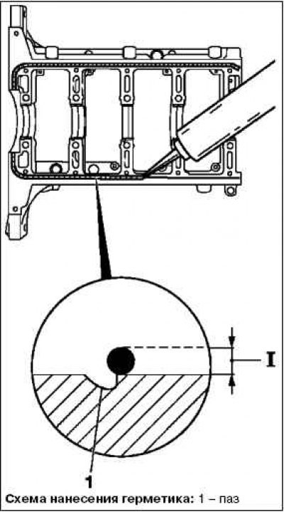
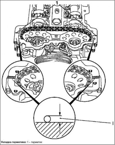
Apply sealant to the outer edges of the groove (dimension I = 2 mm).
Note. Do not apply sealant to the groove.
Note. Complete assembly within 10 minutes.
Attention! Follow the tightening sequence.
Tighten 10 M8 bolts (domestic) torque 25 Nm, tighten by +60°.
Tighten 12 M6 bolts (external) torque 10 Nm, tighten by +60°.
Remove the rest of the seal.
Install the crankshaft rear oil seal. Before this, apply on the working edge (white) silicone grease.
Install special tool KM-235-6 on the crankshaft journal.
Slide the O-ring onto the special tool and press flush using KM-658-1.
Attach the connecting rod bearing caps to the connecting rods with new bolts.
Pressing in the crankshaft rear oil seal: 1 - oil seal; 2 - special device; 3 - special tool for pressing
Note. Pay attention to the installation position, tides (arrow in the picture) on the connecting rod bearing caps must face the gearbox.
Tighten the 8 fastening bolts to a torque of 13 Nm, tighten by +60°+15°.
Note. Always use M6.5 bolts.
Connect the crankshaft pulse sensor harness.
Block the crankshaft by installing the KM 952 special tool.
Smoothly turn the crankshaft until it stops with the KM 952 special tool.
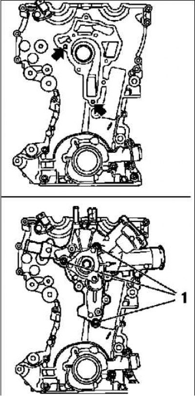
Install a new water pump seal into the timing case.
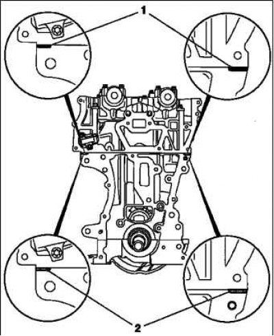
Ensure correct installation of guide bushings (arrows in the picture)

Installing connecting rod bearing caps: 1 - caps
Installing the coolant pump: 1 - mounting bolts
Attach the water pump to the timing case with short bolts.
Tighten 3 mounting bolts to 8 Nm.
Apply sealant.
Sealant laying scheme: 1 - cylinder head gasket; 2 - silicone sealant roller
Note. The timing case must be installed within 10 minutes of applying the silicon sealant (gray).
Turn the engine on the special tool KM 412 by 90°.
Cut off the protruding parts of the elastomer from the cylinder head gasket and replace them with a bead of silicon sealant (gray) 2 mm thick.
Note. Bead of silicone sealant (gray) can be applied directly if there are no elastomer protrusions.
Installation of the gas distribution mechanism
Install a new timing case gasket.
Ensure correct installation of guide bushings (arrows in the picture).
Install the timing chain.
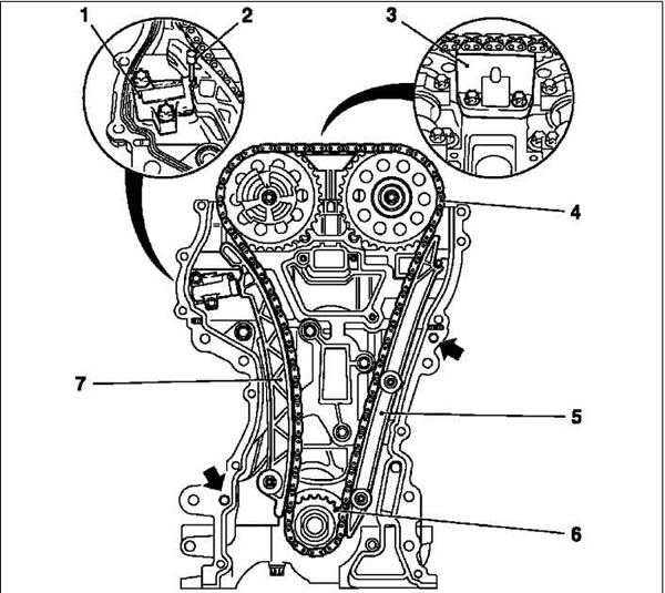
Installation of the gas distribution mechanism: 1 - chain tensioner; 2 - special tool; 3 - guide; 4 – chain of a drive of the gas distribution mechanism; 5 - guide; 6 - drive gear; 7 - clamp bus
Note. When installing, use new camshaft pulley bolts.
Accession of a nave of a cranked shaft: 1 – a belt pulley of a cranked shaft; 2 – a nave of a cranked shaft; 3 - special tool
Ensure correct installation of guide bushings (arrows in the picture).
Install the drive gear.
Install the exhaust camshaft sprocket.
Tighten the mounting bolt.
Install the timing chain.
Note. Provide tension to the drive (release side) branches of the drive chain of the gas distribution mechanism.
Install the intake camshaft pulley into the timing chain with the phase sensor disk and tighten the mounting bolt.
Note. The phase sensor disc must be rotated by hand.
Attach the clamp bar to the cylinder block.
Tighten the fastening bolt to 20 Nm.
Attach the guide to the cylinder block.
Tighten 2 mounting bolts to 8 Nm.
Attach the guide to the cylinder head.
Tighten 2 mounting bolts to 8 Nm.
Loosen the chain tensioner.
Remove special tool KM-955-1.
Attach the timing case.
Tighten the 22 mounting bolts.
Tighten 6 bolts to 8 Nm.
Tighten 14 bolts to 8 Nm.
Tighten 2 bolts to 35 Nm.
Remove special tools KM 952 and KM 953
Note. Special tools must not be used for holding.
Attach the crankshaft hub.
Mark the installation position of the crankshaft hub.
The label must be facing up.
Hold with special tool KM-956-1/-2.
Tighten the bolt to 150 Nm, tighten +45°.
Note. Use a new bolt.
Remove special tool KM-956-1/-2.
Attach the crankshaft pulley.
Tighten 6 mounting bolts to 8 Nm.
Rotate the crankshaft approximately 720°in the direction of engine rotation at the crankshaft hub bolt.
The mark on the crankshaft pulley is set opposite the protrusion on the timing mechanism housing.
In this position, the cams of cylinder No. 1 are located before the TDC (both cams point outward).
Install special tool KM 952. (3)
At the same time, continue to rotate the shaft in the direction of engine rotation by the crankshaft hub bolt until the KM 952 tool stops.
Note. Rotate the crankshaft slowly and smoothly.
In this position, the mark on the crankshaft pulley should align with the protrusion on the timing case.
Install special tool KM 953 on the camshaft.
Alignment of the mark on the crankshaft belt pulley with the protrusion on the timing mechanism housing: 1 - the protrusion on the timing mechanism housing; 2 - mark on the belt pulley; 3 - special tool
Note. If the KM 953 tool cannot be installed, then it is necessary to perform a basic adjustment of the ignition timing.
Note. Adaptation KM 953 must be installed in the grooves of the camshaft until it stops.
Install special tool KM 954 (1) on the phase sensor disc (2) and attach to the timing mechanism housing.

Installing the special tool KM 954 on the phase sensor disk: 1 - special tool; 2 - phase sensor disk
Note. If the KM 953 tool cannot be installed, then it is necessary to perform a basic adjustment of the ignition timing.
Tighten the 2 mounting bolts.
Remove tools KM 954, KM 953 and KM 952.
Install the bolt in the bore of the cylinder block base with a new O-ring and tighten to 60 Nm.
Remove gasket residue and clean sealing surfaces.
Apply sealant.
Note. The cylinder head cover must be installed within 10 minutes after applying the sealant (gray).
Cut off the protruding portion of the timing case gasket flush with the cylinder head/timing case.
Roll on (gray) silicone sealant approx. 2 mm thick (dimension I).
Install the cylinder head cover.
Install a new seal in the cylinder head cover.
Attention! Bolts should be inspected for seal damage. If the seal is damaged, the bolt must be replaced with a new one.
Attach the cylinder head cover to the cylinder head
Tighten 13 mounting bolts to 8 Nm.
Install the ignition module.
Connect the ignition module to the spark plugs.
Tighten 2 mounting bolts to 8 Nm.
Connect the ignition module harness connector.
Attach the ignition module cover to the cylinder head cover.
Connect the engine vent hose to the cylinder head cover.
Attach the pulley to the coolant pump.
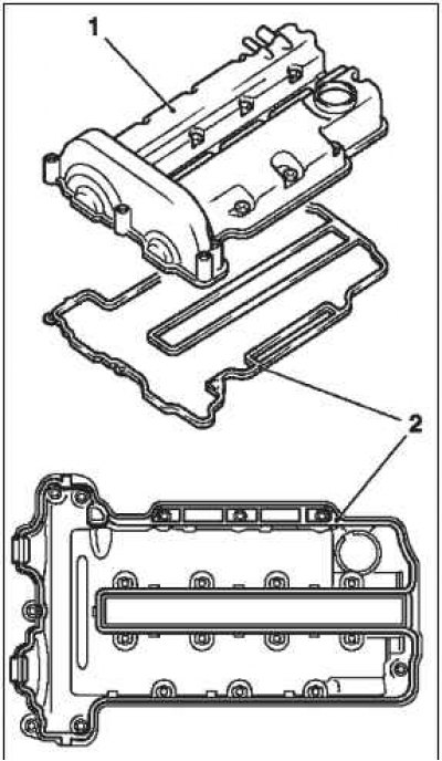
Installation of a cover of a head of the block of cylinders: 1 – a cover; 2 - seal
Tighten 3 mounting bolts to 20 Nm.
Connect the harness connectors for the coolant temperature sensor, camshaft sensor, and oil pressure sensor.
Attach the wire harnesses to the cylinder head cover.
Connect the coolant hoses to the coolant pump and put on 2 clamps.
Attach the thermostat housing with the upper coolant hose to the coolant pump.
Install a new sealing ring.
Tighten 3 mounting bolts to 8 Nm.
Install an alternator.
Install 2 bolted connections and tighten to 35 Nm.
Connect the alternator harness.
Attach the V-ribbed belt tensioner.
Tighten the M8 bolt to 20 Nm.
Tighten the M10 bolt to 55 Nm.
Turn the poly V-belt tensioner in the direction of the arrow (pic. 2.179), using the KM 6131 tool, install the KM 6130 tool.
Install poly V-belt.
Pay attention to the direction of rotation and position of the belt.
Compress the poly V-belt tensioner with KM 6131.
Loosen the V-ribbed belt tensioner.
Attach the engine damping block support to the timing case/cylinder block.
Tighten 3 mounting bolts to 50 Nm.
Install the flywheel.
Lock the flywheel using tool KM 652.
Clean the threads on the crankshaft.
Use new bolts.
Tighten 6 fastening bolts to 35 Nm, tighten by + 30°.
Attach the clutch.
Attach the oil deflector plate to the base of the cylinder block.
Tighten 8 mounting bolts to 8 Nm.
Install the oil pan.
Install a new oil pan seal.
Tighten 16 mounting bolts to 10 Nm.
Add engine oil.
Check the engine oil level and correct if necessary.
Remove the engine from the slipway.
Attach the manual transmission to the engine.
Install the engine.
Visitor comments