
Attention: Before starting work on removing the toothed belt / chain, do not forget to disconnect the cable from the negative terminal of the battery!
General information
The main purpose of the toothed belt / chain is to drive the gas distribution mechanism, while it ensures the coordinated opening / closing of the valves, depending on the current stroke of the operating cycle in each of the engine cylinders. In addition, on various engine models, some auxiliary units, such as high-pressure fuel pumps, are driven by means of a toothed belt / chain (diesel models), a water pump, and on some engines an oil pump. Before removing the belt, it is recommended to draw a diagram of its tension. The sequence of operations for removing and installing the timing belt is almost the same for most engines, the differences are determined by the design features of the engines. If some belt replacement operations are not fully shown, as a rule they are not particularly difficult and require only minimal knowledge of plumbing - refer to the description of the belt replacement procedure on the Z16XEP engine.
It is recommended to replace the belt each time it is removed from the engine. If you plan to reuse the belt, mark with a marker before removing it from the pulleys (in the form of an arrow) to determine the direction of rotation during subsequent installation.
Note: The belt rotates clockwise when looking at the engine from the belt drive side.
chain drive (models Z14XEP, Z22YH, Z13DTH) complicates the procedure for adjusting the valve timing and it differs significantly from carrying out the same with a toothed belt. In this case, contact the company's service station or purchase a special tool from Opel official representatives.
During operation, as a result of weakening the belt / chain, increasing the length, or with some damage to the belt, he / she can jump one or more teeth on the gears / camshaft sprockets, which will lead to a violation of the valve timing, a decrease in engine efficiency, and in in some cases to failure of valves or pistons of cylinders. The valve timing is adjusted with the toothed belt / chain removed by aligning the marks on the camshaft pulleys and the engine crankshaft when setting the TDC position for the corresponding piston (see Section 6).
Attention: When turning the camshafts with the toothed belt/chain removed, none of the pistons must be in the TDC position - otherwise the valves will rest against the piston, which may damage the valves and / or pistons. Turn the engine crankshaft approximately 60°from TDC! The crankshaft can be left unturned if only slight camshaft offset is required.
Note: After replacing the toothed belt, it is recommended to stick a label on the top timing case cover indicating the current mileage and the date of replacement.
Z16XEP engine
Withdrawal
1. Set the piston of the first cylinder to the TDC position of the compression stroke (see Section 6) - Check the installation of the valve timing.
2. Remove the multirib belt (see Section 7).
3. Remove the right engine boot and disconnect the crankshaft pulley (see Section 5).
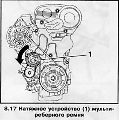
4. Remove the multirib belt tensioner by unscrewing the bolt securing it to the engine block when the device is in the pinned position.
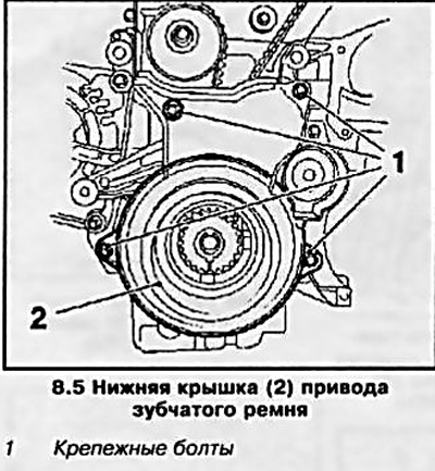
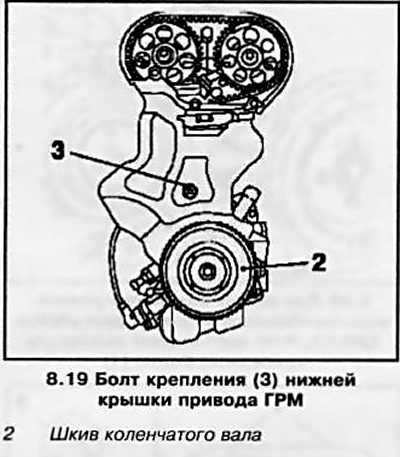
5. Remove the bottom timing belt drive cover (see resist. illustration), by loosening the mounting bolts.
6. Set the TDC position again for the piston of the first cylinder of the engine. check if all labels match (see illustration 8.6, I and III) and fix the position of the camshafts using special tools (see illustration 8.6, I and II).
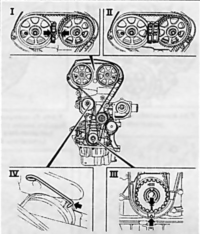
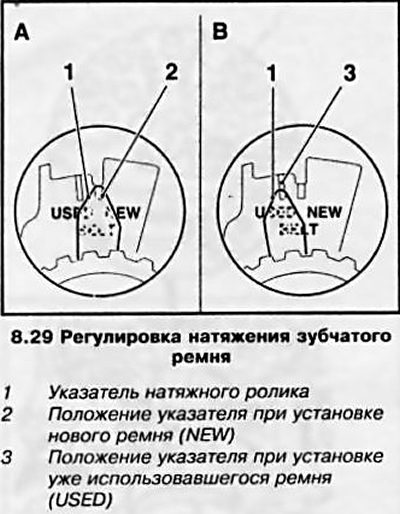
8.6 Removing/installing the toothed belt (Z16XEP engine)
I Checking the alignment of the marks on the camshaft wheels (arrows), installation of the device KM-6340-left
II Installing the KM-6340 fixture-right
III Marks for setting TDC on the crankshaft gear (with pulley removed)
IV Installation with KM-6333 fixture (arrow)
Note: If the marks on the gears do not match, it is not necessary to fix the camshafts.
When removing the toothed belt, the tension roller is pressed clockwise with a socket wrench and fixed with the KM-6333 fixture (see illustration 8.6, IV).
7. If the toothed belt is to be reused, be sure to mark the direction of rotation before removing it. Remove the belt being careful not to damage it when threading it through the engine mount. A belt that has characteristic signs of wear, kinks and damage must be replaced without fail.
8. If, when checking the adjustment of the valve timing, the marks on the gear wheels of the timing mechanism did not match, after removing the belt, align the marks by turning the camshafts accordingly, and fix the shafts from turning with the help of tools (see illustration 8.6, I and II).
Installation
9. Before installing the toothed belt, you must insert it into a special mounting tool that is included with the belt (see resist. illustration). It prevents the belt from being kinked when threaded through the engine mount.
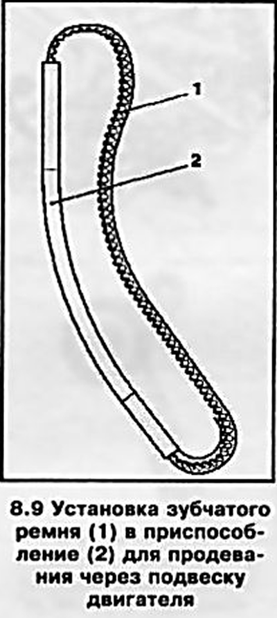
Attention: Kinking can cause the belt to break during operation and cause severe engine damage!
10. Remove the tool and install the toothed belt on the pulleys in the following sequence: exhaust camshaft gear, intake camshaft gear, idler and guide rollers, crankshaft pulley.
11. Remove the retainer from the tension roller - the tension of the toothed belt occurs automatically.
12. Unlock the flywheel if it remains locked after installing the crankshaft pulley (see Section 5), turn the crankshaft 2 turns in the direction of engine rotation (clockwise) and again set the TDC position for the piston of the first cylinder. Check the timing - if necessary, remove and reinstall the toothed belt.
13. Installation of all other removed components is made in an order, the return to an order of removal.
Z18XE engine
Withdrawal
14. Set the piston of the first cylinder to the TDC position of the end of the compression stroke (see Section 6) - Check the installation of the valve timing.
15. Remove the multirib belt (see Section 7).
16. Remove the right front wheel (see Introduction) and right engine boot (see Section 5).
17. Remove the multirib belt tensioner by removing it from the alternator bracket (see resist. illustration).
18. Remove the crankshaft pulley (see Section 5).
19. Remove the lower timing cover (see resist. illustration), by unscrewing 1 mounting bolt.
20. Install right engine mount removal tools (see Section 5).
21. Screw the bolt securing the crankshaft pulley and timing gear into place (into the crankshaft).
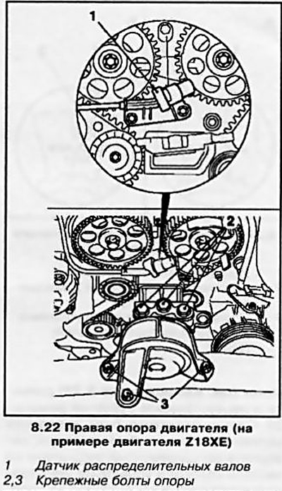
22. Disconnect the camshaft sensor from the cylinder head by unscrewing 2 bolts, and remove the right engine support by unscrewing 6 mounting bolts (see resist. illustration).
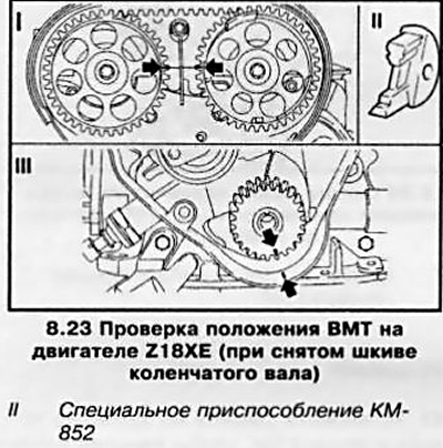
23. Set the TDC position again for the piston of the first cylinder of the engine, check that all marks match (see illustration 8.23, I and III) and fix the position of the camshafts with a special tool (see illustration 8.23, II).
Note: If the marks on the gears do not match, it is not necessary to fix the camshafts.
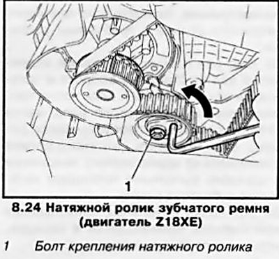
24. Loosen the mounting bolt and turn the toothed belt tensioner (see resist. illustration) behind the adjusting eccentric in the opposite direction of the arrow (clockwise) tighten the bolt until the tension roller pointer is in front of the left stop. If necessary, mark the direction of rotation of the belt and remove it.
25. If, when checking the adjustment of the valve timing, the marks on the gears of the timing mechanism did not match, after removing the belt, set the marks to the desired position by turning the camshafts and fix them with a special tool (see illustration 8.23, II).
Installation
26. Install the belt on the wheels and rollers so that the pulling branch (right) has been tightened, be sure to check the direction of rotation of the belt.
27. After replacing / removing the belt, it is necessary to adjust its tension. To do this, loosen the mounting bolt and turn the toothed belt tensioner (see illustration 8.24) behind the adjusting eccentric in the direction of the arrow so that the tension roller pointer is in front of the right stop, tighten the bolt.
28. Remove the KM-852 tool, smoothly rotate the crankshaft 2 full turns clockwise and set the piston of the first cylinder to the TDC position. To control the position, install the KM-852 fixture again; if adjustment is not required, remove it. When labels do not match (see illustration 8.23) remove and reinstall the toothed belt.
29. Slightly loosen the toothed belt tensioning roller bolt, turn the adjusting eccentric clockwise and set the tensioning roller pointer as shown in resist. illustrations. Tighten the idler pulley mounting bolt to the required torque.
30. Once again smoothly rotate the crankshaft 2 full turns and set the TDC position. If, after cranking the crankshaft, the timing marks did not match, reinstall the belt, if the tension roller pointer deviated from the standard position, repeat the procedure for tensioning the toothed belt.
31. Installation of other removed components is made in an order, the return to an order of removal.
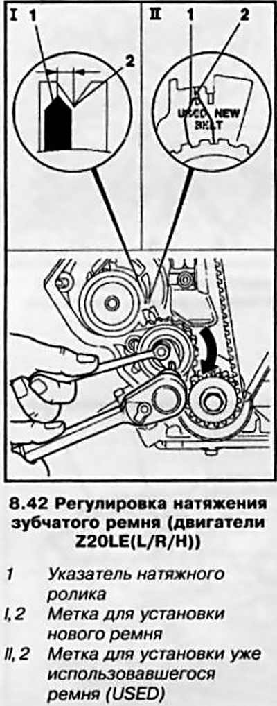
Z20LE engines (L/R/H)
Withdrawal
32. Set the piston of the first cylinder to the TDC position of the end of the compression stroke (see Section 6) - Check the installation of the valve timing.
33. Remove the multirib belt (see Section 7).
34. Remove the engine boot, wring out the tension roller of the multirib belt and fix it with a suitable pin.
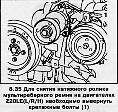
35. Turn out 2 fixing bolts (see resist. illustration) and remove the tension roller.
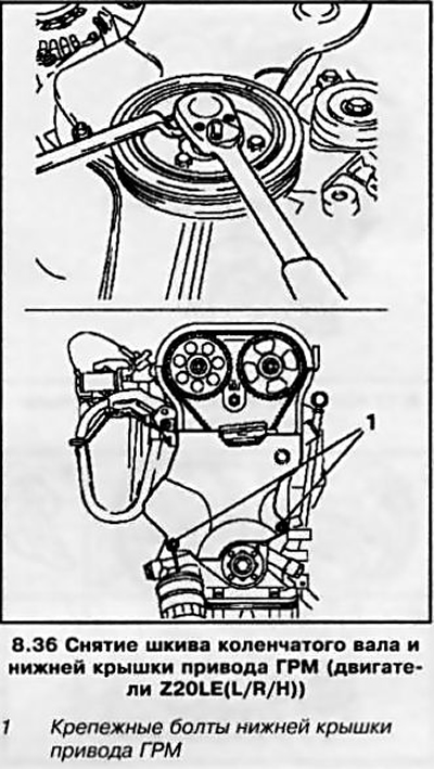
36. Remove the crankshaft pulley by unscrewing the 4 mounting bolts, holding the shaft from turning with a socket wrench (see resist. illustration). Remove the 2 mounting bolts and remove the lower timing cover.
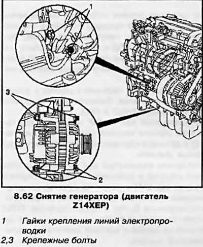
37. Install the right engine mount removal tool (see Section 5) and remove the support by unscrewing the 6 fixing bolts (see illustration 8.22).
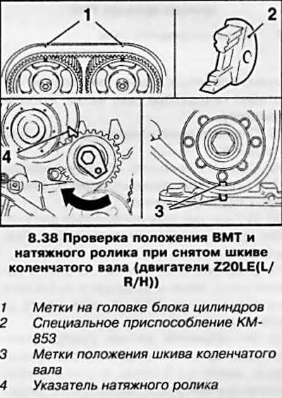
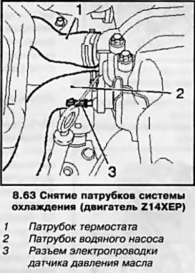
38. Check the TDC position of the camshaft and crankshaft (see resist. illustration) All labels must match. Fix the position of the camshaft gears with the KM-853 tool.
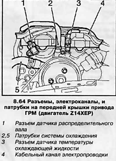
Note: If the marks on the wheels do not match, it is not necessary to fix the camshafts.
39. Loosen the toothed belt, to do this, release the tension roller mounting bolt and turn the adjusting eccentric with the socket wrench in the direction of the arrow (see illustration 8.38) so that the tension roller pointer is near the left stop, tighten the bolt. If necessary, mark the direction of rotation of the belt and remove it.
40. If, when checking the adjustment of the valve timing, the marks on the gears of the timing mechanism did not match, after removing the belt, align the marks by turning the camshafts to the desired position and fix them with a special tool KM-853.
Installation
41. Install the belt on the gears and rollers so that the pulling branch (right) has been tightened, be sure to check the direction of rotation of the belt.
42. After replacing / removing the belt, it is necessary to adjust its tension. The adjustment is carried out similarly to the same operation for the Z18XE engine (see paragraphs 27-30). Depending on the configuration, two types of adjusting devices can be installed on the engines (see resist. illustration). In the first version, when installing a new belt, the pointer should be set to the center mark (cutout), and when installing an already used one - 4 mm to the left of this mark. In the second version, both positions have corresponding labels - «NEW» /USED» («NEW» / «USED»).
43. Installing the remaining removed components is carried out in the reverse order of removal.
Z17DT engines (L/H)
Withdrawal
44. Perform the operations described in paragraphs 45-49, Section 6. After removing the air cleaner, remove the multi-ribbed belt (see Section 7).
45. Remove the engine crankcase protection and install the tool for removing the right engine support (see Section 5).
46. Remove the crankshaft pulley by removing the 4 mounting bolts while holding the pulley from turning by the crankshaft center pin with a hex wrench.
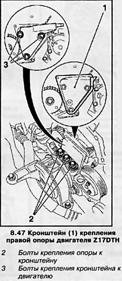
47. Remove the right engine mount by unscrewing the 6 mounting bolts (see resist. illustration) and dismantle the bracket for fixing the right support.
48. Remove the engine cooling water pump drive pulley by unscrewing 3 bolts (see chapter 3).
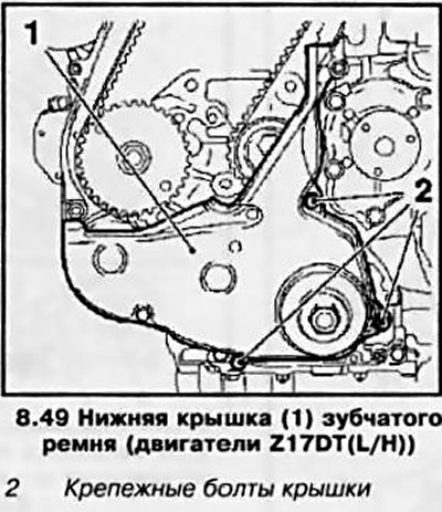
49. Remove the bottom timing belt cover (see resist. illustration).
50. Set the piston of the first cylinder to the TDC position of the end of the compression stroke (see Section 6).
51. Mark the direction of rotation of the toothed belt, loosen the fixing bolt of the tension roller (see resist. illustration) and using an open-end wrench, press the roller in the direction of the arrow, loosen the belt and tighten the roller fixing bolt in the depressed position. Remove the belt.
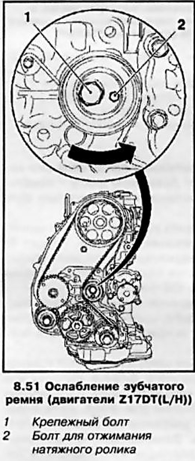
Installation
52. Install the toothed belt observing the direction of rotation on the gear wheels of the drive in the order of priority indicated by the arrow (see resist. illustration). Note: The injection pump and timing drive wheels must be fixed with bolts, the marks on the crankshaft mounting flange and the oil pump housing must match.
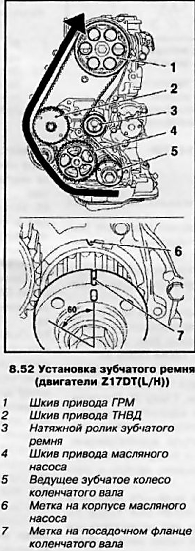
53. Loosen the tension roller mounting bolt and release the roller - the belt will tighten. Unscrew the adjusting bolts of the gears of the injection pump and timing.
54. Rotate the crankshaft 60°against the direction of shaft rotation (counterclock-wise) (see illustration 8.52) and tighten the tension roller mounting bolt to the required torque.
55. Smoothly rotate the crankshaft 2 full turns clockwise and set the piston of the first cylinder to the TDC position - the marks on the crankshaft flange and the oil pump housing must match. Screw the adjusting bolts into the pulleys of the injection pump and timing drive - if at least one of the bolts is not screwed in (the holes on the pulley and the motor housing did not match), reinstall the toothed belt.
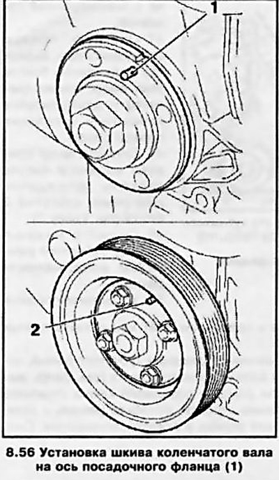
56. Installation of removed and disconnected components is carried out in the reverse order of dismantling. When installing the crankshaft pulley, it is necessary to align the axis of the mounting flange with the hole in the pulley (see resist. illustration), do not forget to replace the pulley mounting bolts. Tighten all fasteners to the required torque (see specs). Upon completion of work, check the coolant level and, if necessary, make appropriate adjustments.
Engine Z19DTH
57. When installing a toothed belt, place it on the gear wheels so that its pulling side is taut (see resist. illustration). At the same time, observe the specified direction of rotation of the toothed belt (clockwise).
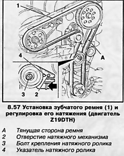
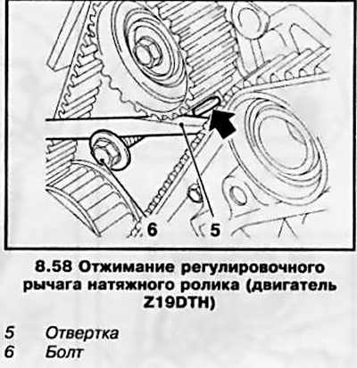
58. The tension of the toothed belt is done with the help of an assistant, for which screw in the bolt to use it as a support (see resist. illustration), and press the adjusting lever with a screwdriver in the direction of the arrow so that the tension roller pointer is opposite the hole. Tighten the mounting bolt.
59. Turn the crankshaft 2 full turns clockwise and set the TDC position for the piston of the first cylinder. Loosen the idler pulley mounting bolt and re-adjust the toothed belt tension. After that, tighten the roller mounting bolt with a force of 25 Nm.
Z14XEP engine
Withdrawal
60. Drain the coolant from the engine cooling system (see chapter 3) and remove the engine oil pan (see Section 12).
61. Remove the multi-rib belt and the multi-rib belt tensioner (see Section 7).
62. Remove the generator, for which disconnect the wiring lines and unscrew the mounting bolts (see resist. illustration). (See also Chapter 5).
63. Disconnect the cooling system pipe from the thermostat housing and remove the thermostat (see chapter 3). Disconnect the pipe from the water pump and the wiring connector from the oil pressure sensor (see resist. illustration.
64. Disconnect all indicated on the resist. illustrations of connectors, channels and branch pipes.
65. Remove the water pump pulley and remove the water pump (see chapter 3). Make sure the two guide bushings stay in place.
Attention: The fixing bolts of the water pump have different lengths - mark the positions of the three short bolts!
66. Set the piston of the first cylinder to the TDC position (see Section 6) after checking the position of the camshafts, remove the tools KM-953 and KM-954.
67. Remove the crankshaft pulley by unscrewing 6 bolts, holding the shaft from turning by the head of the central bolt.
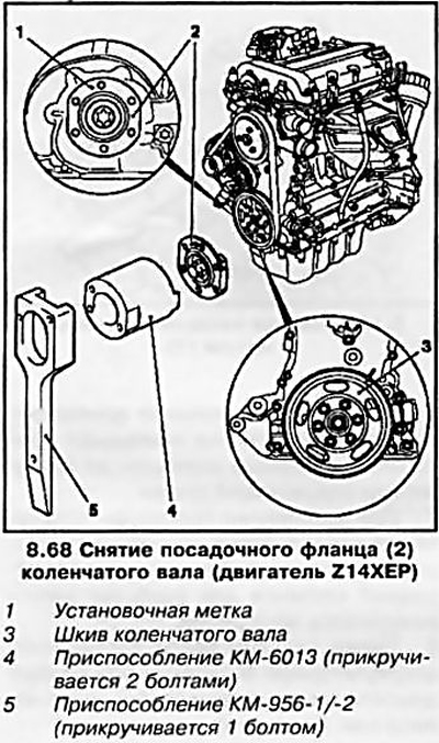
68. Loosen the central bolt of the crankshaft mounting flange, for which install a special tool (see resist. illustration) to keep the shaft from turning.
Note: When performing this operation, use the help of an assistant. The KM-952 fixture must be removed from the mounting hole.
69. Install the KM-952 tool again, completely unscrew the central bolt and remove the mounting flange.
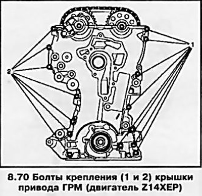
70. Turn out 15 fixing bolts (see resist. illustration) and remove the timing cover.
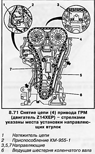
71. Pull back and fix the chain tensioner using the KM-355-1 tool (see resist. illustration). Remove guides (alternately - (3), (5), (7)) and remove the chain from the crankshaft drive sprocket. Remove the timing cover gasket. clean mating surfaces.
72. Carefully remove the crankshaft front oil seal from the timing cover seat using a suitable tool - do not damage the seating surfaces.
Note: The oil seal must be replaced every time the timing chain is replaced/removed.
Installation
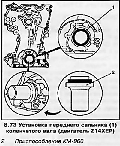
73. Lubricate the outer surfaces of the new oil seal with silicone grease (white) and install the oil seal using the KM-960 tool (see resist. illustration) into the seat of the timing cover.
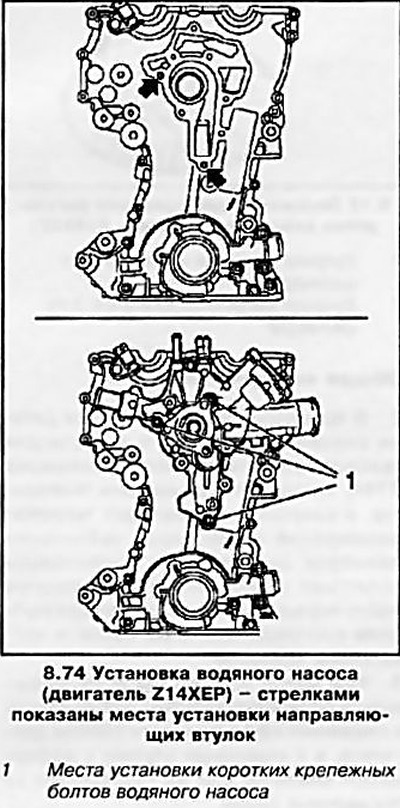
74. Remove the remnants of the old from the timing cover and install a new water pump gasket on the cleaned surface - make sure that the guide bushings are installed correctly (see resist. illustration). Install the water pump to the drive cover, securing it with 3 short bolts.
75. Remove elastomer pads (see resist. illustration) joints of the block head with the cylinder block and replace with new ones, having previously lubricated them with silicone sealant (gray color), by applying a bead of sealant approximately 2 mm thick. In the absence of elastomer gaskets, the joints of the mating surfaces can be filled with sealant without installing gaskets.
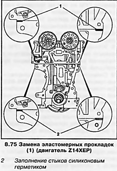
Attention: Installation of the timing cover must be completed within 10 minutes after applying the sealant!
76. Install a new timing cover gasket on the engine - make sure the guide bushings are installed correctly (see illustration 8.74).
77. Install the crankshaft drive sprocket on the shaft and install the timing chain on it on the camshaft sprockets - pulling (right) the chain branch must be taut. Install the guides in the reverse order of their removal (see paragraph 71).
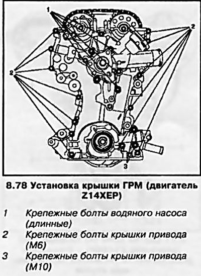
78. Install the timing cover and tighten alternately, in accordance with that indicated on the resistance. illustrations by numbering, fixing bolts.
79. Remove adjusting devices KM-952 and KM-953 from the engine. With the help of special devices (see above) install the crankshaft mounting flange - alignment mark (see illustration 8.68) should be at the top.
80. Check and adjust the valve timing (see Section 6) and reinstall the remaining components that were removed in the reverse order of their removal. Pour oil into the lubrication system and coolant into the engine cooling system, check the systems for leaks.
Visitor comments